Nissan Juke Service and Repair Manual : Door mirror (open/close motor)
Component Function Check
1.CHECK DOOR MIRROR RETRACT FUNCTION
1. Turn ignition switch ON.
2. Operate open/close switch. Check that door mirror operates normally.
Is the inspection result normal? YES >> INSPECTION END
NO >> Refer to MIR-25, "Diagnosis Procedure".
Diagnosis Procedure
1.CHECK DOOR MIRROR REMOTE CONTROL SWITCH POWER SUPPLY
1. Turn ignition switch OFF.
2. Disconnect door mirror remote control switch connector.
3. Turn ignition switch ON.
4. Check voltage between door mirror remote control switch harness connector and ground.

Is the inspection result normal? YES >> GO TO 3.
NO >> GO TO 2.
2.DETECT MALFUNCTIONING PART
Check the following.
• 10 A fuse (#19)
• Harness for open or short between door mirror remote control switch harness
connector and battery terminal.
Is the inspection result normal? YES >> GO TO 11.
NO >> Repair or replace the malfunctioning parts.
3.CHECK DOOR MIRROR REMOTE CONTROL SWITCH GROUND CIRCUIT
1. Turn ignition switch OFF.
2. Check continuity between door mirror remote control switch harness connector and ground.

Is the inspection result normal? YES >> GO TO 4.
NO >> Repair or replace harness or connector.
4.CHECK DOOR MIRROR OPEN RELAY AND DOOR MIRROR CLOSE RELAY INPUT SIGNAL
1. Connect door mirror remote control switch connector.
2. Disconnect door mirror open relay and door mirror close relay connector.
3. Turn ignition switch ON.
4. Check voltage between door mirror open relay and door mirror close relay harness connector and ground.

Is the inspection result normal? YES >> GO TO 6.
NO >> GO TO 5.
5.CHECK HARNESS CONTINUITY-1
1. Turn ignition switch OFF.
2. Disconnect door mirror remote control switch connector.
3. Check continuity between door mirror remote control switch harness connector and door mirror open/ close relay harness connector.

4. Check continuity between door mirror remote control switch harness connector and ground.

Is the inspection result normal? YES >> GO TO 10.
NO >> Repair or replace harness.
6.CHECK DOOR MIRROR MOTOR INPUT SIGNAL
1. Turn ignition switch OFF.
2. Connect door mirror open relay and door mirror close relay connector.
3. Disconnect door mirror (driver side) connector and door mirror (passenger side) connector.
4. Turn ignition switch ON.
5. Check voltage between door mirror connector and ground.

Is the inspection result normal?
YES >> GO TO 8.
NO >> GO TO 7.
7.CHECK HARNESS CONTINUITY-2
1. Turn ignition switch OFF.
2. Disconnect door mirror open relay connector and door mirror close relay connector.
3. Check continuity between door mirror harness connector and door mirror open relay and door mirror close relay harness connector.

4. Check continuity between door mirror harness connector and ground.

Is the inspection result normal? YES >> GO TO 8.
NO >> Repair or replace harness.
8.CHECK DOOR MIRROR OPEN RELAY
Check door mirror open relay.
Refer to MIR-28, "Component Inspection (Door Mirror Open Relay)".
Is the inspection result normal? YES >> GO TO 9.
NO >> Replace door mirror open relay.
9.CHECK DOOR MIRROR CLOSE RELAY
Check door mirror close relay.
Refer to MIR-28, "Component Inspection (Door Mirror Close Relay)".
Is the inspection result normal? YES >> GO TO 10.
NO >> Replace door mirror close relay.
10.CHECK DOOR MIRROR REMOTE CONTROL SWITCH
Check door mirror remote control switch (open/close switch).
Refer to MIR-28, "Component Inspection (Door Mirror Remote Control Switch)".
Is the inspection result normal? YES >> Replace door mirror open/close motor.
NO >> Replace door mirror remote control switch.
11.CHECK INTERMITTENT INCIDENT
Refer to GI-42, "Intermittent Incident".
>> INSPECTION END
Component Inspection (Door Mirror Remote Control Switch)
1.CHECK OPEN/CLOSE SWITCH
1. Turn ignition switch OFF.
2. Disconnect door mirror remote control switch connector.
3. Check door mirror remote control switch

Is the inspection result normal? YES >> INSPECTION END.
NO >> Replace door mirror remote control switch.
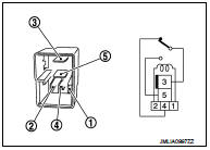
Component Inspection (Door Mirror Open Relay)
1.CHECK DOOR MIRROR OPEN RELAY
1. Turn ignition switch OFF.
2. Remove door mirror open relay.
3. Check the continuity between door mirror open relay terminals under the following conditions.


Is the inspection result normal? YES >> INSPECTION END.
NO >> Replace door mirror open relay.
Component Inspection (Door Mirror Close Relay)
1.CHECK DOOR MIRROR OPEN/CLOSE RELAY
1. Turn ignition switch OFF.
2. Remove door mirror close relay.
3. Check the continuity between door mirror close relay terminals under the following conditions.

Is the inspection result normal? YES >> INSPECTION END
NO >> Replace door mirror close relay.
 Door mirror remote control switch (mirror switch/
changeover switch)
Door mirror remote control switch (mirror switch/
changeover switch)
Component Inspection
1.CHECK MIRROR SWITCH & CHANGEOVER SWITCH
1. Turn ignition switch OFF.
2. Disconnect door mirror remote control switch connector.
3. Check door mirror remote control switc ...
 Auto retractable door mirror circuit
Component Function Check
1.CHECK FUNCTION
1. Turn the door mirror open/close switch to “AUTO”.
2. Turn ignition switch ON.
3. Select “INTELLIGENT KEY” of “BCM” using CONSULT-III.
4. Select “RETRA ...
Other materials:
Headlamp aiming system (manual)
Component Inspection
1.CHECK HEADLAMP AIMING SWITCH
1. Remove headlamp aiming switch.
2. Check resistance among each headlamp aiming switch terminal.
Is the inspection result normal?
YES >> Headlamp aiming switch is normal.
NO >> Replace the headlamp aiming switch.
...
Diagnosis system (navi control unit)
Diagnosis Description
On-Board Diagnosis Item
• On-board diagnosis is performed in service test mode.
• On-board diagnosis checks if the system operates normally.
Service test mode
METHOD OF STARTING
1. Start the engine.
2. Turn OFF audio.
3. While pressing the “SET UP” switch, turn th ...
System
POWER DISTRIBUTION SYSTEM
POWER DISTRIBUTION SYSTEM : System Description
SYSTEM DESCRIPTION
• PDS (POWER DISTRIBUTION SYSTEM) is the system that BCM controls with the
operation of the pushbutton
ignition switch and performs the power distribution to each power circuit. This
system is used in ...