Nissan Juke Service and Repair Manual : Auto retractable door mirror circuit
Component Function Check
1.CHECK FUNCTION
1. Turn the door mirror open/close switch to “AUTO”.
2. Turn ignition switch ON.
3. Select “INTELLIGENT KEY” of “BCM” using CONSULT-III.
4. Select “RETRACTABLE MIRROR” in “ACTIVE TEST” mode.
5. Touch “On” check that it works normally.
Is the inspection result normal? YES >> INSPECTION END
NO >> Refer to MIR-30, "Diagnosis Procedure"
Diagnosis Procedure
1.CHECK DOOR MIRROR OPEN RELAY AND DOOR MIRROR CLOSE RELAY POWER SUPPLY
1. Turn ignition switch OFF.
2. Disconnect door mirror open relay and door mirror close relay connector.
3. Check voltage between door mirror open relay and door mirror close relay harness connector and ground.

Is the inspection result normal? YES >> GO TO 3.
NO >> GO TO 2.
2.DETECT MALFUNCTIONING PART
Check the following.
• 10 A fuse (#7)
• Harness for open or short between door mirror remote control switch harness
connector and battery terminal.
Is the inspection result normal? YES >> GO TO 8.
NO >> Repair or replace the malfunctioning parts.
3.CHECK BCM INPUT SIGNAL CIRCUIT
1. Disconnect BCM connector.
2. Check continuity between door mirror open relay and door mirror close relay harness connector and BCM harness connector

3. Check continuity between BCM harness connector and ground.

Is the inspection result normal? YES >> GO TO 4.
NO >> Repair or replace harness or connector.
4.CHECK OPEN/CLOSE MOTOR GROUND CIRCUIT
1. Disconnect door mirror remote control switch connector.
2. Check continuity between door mirror remote control switch harness connector and door mirror open relay harness connector.

3. Check continuity between door mirror remote control switch harness connector and ground.

Is the inspection result normal? YES >> GO TO 5.
NO >> Repair or replace harness.
5.CHECK DOOR MIRROR OPEN RELAY
Check door mirror open relay.
Refer to MIR-32, "Component Inspection (Door Mirror Open Relay)" Is the inspection result normal? YES >> GO TO 7.
NO >> Repair or replace harness or connector.
6.CHECK DOOR MIRROR CLOSE RELAY
Check door mirror close relay.
Refer to MIR-32, "Component Inspection (Door Mirror Close Relay)" Is the inspection result normal? YES >> GO TO 7.
NO >> Repair or replace harness or connector.
7.CHECK BCM FUNCTION
1. Turn the door mirror open/close switch to AUTO.
2. Connect door mirror remote control switch connector, door mirror open relay, door mirror close relay and BCM connector.
3. Turn ignition switch ON.
4. Select “INTELLIGENT KEY” of “BCM” using CONSULT-III.
5. Select “RETRACTABLE MIRROR” in “ACTIVE TEST” mode.
6. Touch “On” and check voltage between BCM harness connector and ground.

Is the inspection result normal? YES >> GO TO 8.
NO >> Replace BCM. Refer to BCS-93, "Removal and Installation".
8.CHECK INTERMITTENT INCIDENT
Refer to GI-42, "Intermittent Incident"
>> INSPECTION END
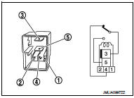
Component Inspection (Door Mirror Open Relay)
1.CHECK DOOR MIRROR OPEN RELAY
1. Turn ignition switch OFF.
2. Remove door mirror open relay.
3. Check the continuity between door mirror open relay terminals under the following conditions.


Is the inspection result normal? YES >> INSPECTION END.
NO >> Replace door mirror open relay.
Component Inspection (Door Mirror Close Relay)
1.CHECK DOOR MIRROR OPEN/CLOSE RELAY
1. Turn ignition switch OFF.
2. Remove door mirror close relay.
3. Check the continuity between door mirror close relay terminals under the following conditions.

Is the inspection result normal? YES >> INSPECTION END.
NO >> Replace door mirror close relay.
 Door mirror (open/close motor)
Component Function Check
1.CHECK DOOR MIRROR RETRACT FUNCTION
1. Turn ignition switch ON.
2. Operate open/close switch. Check that door mirror operates normally.
Is the inspection result normal? ...

Other materials:
Refilling
1. Remove filler plug (1) and gasket. Then fill oil up to mounting
hole for the filler plug.
: Vehicle front
Oil and viscosity : Refer to MA-13, "Fluids
and Lubricants".
Oil capacity : Refer to DLN-117, "General
Specifications".
CAUTION:
Carefully fill the oil. (Fill up ...
ASCD steering switch
Component Function Check
1.CHECK ASCD STEERING SWITCH FUNCTION
1. Turn ignition switch ON.
2. Check the voltage between ECM harness connector terminals under the following
conditions.
Is the inspection result normal?
YES >> INSPECTION END
NO >> Go to EC-1011, "Diagnosis Pr ...
Precaution for Supplemental Restraint System (SRS) "AIR BAG" and "SEAT BELT
PRE-TENSIONER"
The Supplemental Restraint System such as “AIR BAG” and “SEAT BELT PRE-TENSIONER”,
used along
with a front seat belt, helps to reduce the risk or severity of injury to the
driver and front passenger for certain
types of collision. Information necessary to service the system safely is
include ...