Nissan Juke Service and Repair Manual : P1614 chain of IMMU-KEY
DTC Logic
DTC DETECTION LOGIC

DTC CONFIRMATION PROCEDURE
1.PERFORM DTC CONFIRMATION PROCEDURE 1
1. Contact Intelligent Key backside to push-button ignition switch.
2. Check DTC in “Self Diagnostic Result” mode of “ENGINE” using CONSULT-III.
Is DTC detected? YES >> Go to SEC-55, "Diagnosis Procedure".
NO >> GO TO 2.
2.PERFORM DTC CONFIRMATION PROCEDURE 2
1. Press the push-button ignition switch.
2. Check DTC in “Self Diagnostic Result” mode of “ENGINE” using CONSULT-III.
Is DTC detected? YES >> Go to SEC-55, "Diagnosis Procedure".
NO >> INSPECTION END
Diagnosis Procedure
1.CHECK FUSE
1. Turn ignition switch OFF.
2. Check that the following fuse in IPDM E/R is not blown.

Is the fuse fusing? YES >> Replace the blown fuse after repairing the cause of blowing.
NO >> GO TO 2.
2.CHECK NATS ANTENNA AMP. POWER SUPPLY
1. Disconnect NATS antenna amp. connector.
2. Check voltage between NATS antenna amp. harness connector and ground.

Is the inspection result normal? YES >> GO TO 4.
NO >> GO TO 3.
3.CHECK NATS ANTENNA AMP. POWER SUPPLY CIRCUIT
1. Disconnect IPDM E/R connector.
2. Check continuity between IPDM E/R harness connector and NATS antenna amp. connector

3. Check continuity between IPDM E/R harness connector and ground.

the inspection result normal? YES >> Replace IPDM E/R. Refer to PCS-34, "Removal and Installation".
NO >> Repair or replace harness.
4.CHECK NATS ANTENNA AMP. OUTPUT SIGNAL 1
1. Connect NATS antenna amp. connector.
2. Disconnect BCM connector.
3. Check voltage between BCM harness connector and ground.

Is the inspection result normal? YES >> GO TO 6.
NO >> GO TO 5.
5.CHECK NATS ANTENNA AMP. OUTPUT SIGNAL CIRCUIT 1
1. Disconnect NATS antenna amp. connector.
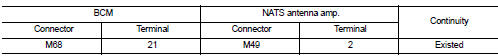
2. Check continuity between BCM harness connector and NATS antenna amp. connector.
3. Check continuity between BCM harness connector and ground.

Is the inspection result normal? YES >> Replace NATS antenna amp. Refer to SEC-167, "Removal and Installation".
NO >> Repair or replace harness.
6.CHECK NATS ANTENNA AMP. COMMUNICATION SIGNAL 1
1. Connect BCM connector.
2. Check voltage between BCM harness connector and ground using analog tester.

Is the inspection result normal?
YES >> GO TO 7.
NO >> Replace NATS antenna amp. Refer to SEC-167, "Removal and Installation".
7.CHECK NATS ANTENNA AMP. OUTPUT SIGNAL 2
1. Disconnect BCM connector.
2. Check voltage between BCM harness connector and ground.

Is the inspection result normal? YES >> GO TO 9.
NO >> GO TO 8.
8.CHECK NATS ANTENNA AMP. OUTPUT SIGNAL CIRCUIT 2
1. Disconnect NATS antenna amp. connector.
2. Check continuity between BCM harness connector and NATS antenna amp. connector.

3. Check continuity between BCM harness connector and ground.

Is the inspection result normal? YES >> Replace NATS antenna amp. Refer to SEC-167, "Removal and Installation".
NO >> Repair or replace harness.
9.CHECK NATS ANTENNA AMP. COMMUNICATION SIGNAL 2
1. Connect BCM connector.
2. Check voltage between BCM harness connector and ground using analog tester.

Is the inspection result normal? YES >> GO TO 10.
NO >> Replace NATS antenna amp. Refer to SEC-167, "Removal and Installation".
10.CHECK NATS ANTENNA AMP. GROUND CIRCUIT
1. Disconnect NATS antenna amp. connector.
2. Check continuity between NATS antenna amp. harness connector and ground.

Is the inspection result normal?
YES >> GO TO 11.
NO >> Repair or replace harness.
11.CHECK INTERMITTENT INCIDENT
Refer to GI-42, "Intermittent Incident".
>> INSPECTION END
 P1612 chain of ECM-IMMU
DTC Logic
DTC DETECTION LOGIC
NOTE:
• If DTC P1612 is displayed with DTC U1000 (for BCM), first perform the trouble
diagnosis for DTC U1000.
Refer to BCS-83, "DTC Logic".
• If DTC ...
 P1616 ECM
DTC Logic
DTC DETECTION LOGIC
DTC CONFIRMATION PROCEDURE
1.PERFORM DTC CONFIRMATION PROCEDURE FOR MALFUNCTION
1. Turn ignition switch ON amd wait 2 seconds or more.
2. Check DTC in “Self Diagno ...
Other materials:
Component parts
INTERIOR LIGHTING SYSTEM
INTERIOR LIGHTING SYSTEM : Component Parts Location
1. IPDM E/R
Refer to PCS-5, "Component Parts
Location"
2. BCM
Refer to BCS-6, "BODY CONTROL
SYSTEM : Component Parts Location"
3. Door lock and unlock switch
4. Front door request switch (driv ...
Exhaust manifold
Exploded View
1. Stud bolt
2. Exhaust manifold cover
3. Exhaust manifold
4. Gasket
Engine front
: N·m (kg-m, ft-lb)
: N·m (kg-m, in-lb)
: Always replace after every
disassembly.
Removal and Installation
REMOVAL
1. Drain engine coolant. Refer to CO-11, "Draining".
2. Remo ...
B260F Engine status
Description
BCM receives the engine status signal from ECM via CAN communication.
DTC Logic
DTC DETECTION LOGIC
NOTE:
• If DTC B260F is displayed with DTC U1000, first perform the trouble diagnosis
for DTC U1000. Refer to
BCS-83, "DTC Logic".
• If DTC B260F is displayed with DTC U ...