Nissan Juke Service and Repair Manual : Operation
Switch Name and Function
OPERATION AND DISPLAY
A/C Display (Display in Multi Display Unit)

• Air conditioning system operation status is indicated on display in multi display unit. Indication of air conditioning system varies according to display mode of multi display unit. For changing procedure of display mode, refer to AV-99, "NISSAN DYNAMIC CONTROL SYSTEM : System Description".
- In CLIMATE mode: Operation status of air conditioning system (setting temperature, air flow, and “AUTO”*1) is indicated on display when air conditioning system is turned ON.
- In D-MODE: Operation status of air conditioning system (setting temperature, A/C switch, and “AUTO”*2) is indicated on lower portion of display when air conditioning system is turned ON.
NOTE
:
*1: AUTO is indicated when both air flow and air outlet are in automatic
control.
*2: Air Flow is indicated when air flow or air outlet is in manual control.
A/C Controller (Multi Display Unit) Operation procedure of air conditioning system varies depending on display mode of multi display unit. For changing procedure of display mode, refer to AV-99, "NISSAN DYNAMIC CONTROL SYSTEM : System Description".
• In CLIMATE mode: All operations of air conditioning system are possible.
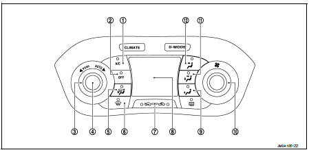
1. A/C switch
2. OFF switch
3. Temperature control dial
4. AUTO switch
5. MODE switch (D/F)
6. DEF switch
7. Intake switch
8. Display
9. MODE switch (FOOT)
10. Fan control dial
11. MODE switch (B/L)
12. MODE switch (VENT)


• In D-MODE: The following switches and dial cannot be operated.
- A/C switch
- OFF switch
- MODE switch
- Fan control dial
 System
System Diagram
System Description
DESCRIPTION
• Automatic air conditioning system is controlled by each function of A/C
auto amp., BCM, ECM and IPDM E/
R.
• Each operation of air conditioning ...
 Diagnosis system (A/C auto AMP.)
Description
Air conditioning system performs self-diagnosis, operation check, function
diagnosis, and various settings
using diagnosis function of each control unit.
CONSULT-III Function
CONSU ...
Other materials:
P1550 battery current sensor
DTC Logic
DTC DETECTION LOGIC
DTC CONFIRMATION PROCEDURE
1.PRECONDITIONING
If DTC Confirmation Procedure has been previously conducted, always perform
the following before conducting
the next test.
1. Turn ignition switch OFF and wait at least 10 seconds.
2. Turn ignition switch ON.
3. ...
Removal and Installation Procedure for CVT Unit Connector
REMOVAL
• Rotate bayonet ring (A) counterclockwise. Pull out CVT unit harness
connector (B) upward and remove it.
INSTALLATION
1. Align marking (A) on CVT unit harness connector terminal with
marking (B) on bayonet ring. Insert CVT unit harness connector.
2. Rotate bayonet ring clockwise.
...
Both side headlamps (HI) are not turned on
Description
Both side headlamps (HI) are not turned ON when setting to the lighting
switch HI or PASS.
Diagnosis Procedure
1.COMBINATION SWITCH INSPECTION
Check the combination switch. Refer to BCS-92, "Symptom Table".
Is the inspection result normal?
YES >> GO TO 2.
NO ...