Nissan Juke Service and Repair Manual : P1550 battery current sensor
DTC Logic
DTC DETECTION LOGIC

DTC CONFIRMATION PROCEDURE
1.PRECONDITIONING
If DTC Confirmation Procedure has been previously conducted, always perform the following before conducting the next test.
1. Turn ignition switch OFF and wait at least 10 seconds.
2. Turn ignition switch ON.
3. Turn ignition switch OFF and wait at least 10 seconds.
TESTING CONDITION:
Before performing the following procedure, confirm that battery voltage is more
than 8 V at idle.
>> GO TO 2.
2.PERFORM DTC CONFIRMATION PROCEDURE
1. Start engine and wait at least 10 seconds.
2. Check 1st trip DTC.
Is 1st trip DTC detected? YES >> Proceed to EC-701, "Diagnosis Procedure".
NO >> INSPECTION END
Diagnosis Procedure
1.CHECK BATTERY CURRENT SENSOR POWER SUPPLY
1. Turn ignition switch OFF.
2. Disconnect battery current sensor harness connector.
3. Turn ignition switch ON.
4. Check the voltage between battery current sensor harness connector and ground.

Is the inspection result normal? YES >> GO TO 3.
NO >> GO TO 2.
2.CHECK SENSOR POWER SUPPLY CIRCUIT
1. Turn ignition switch OFF.
2. Disconnect ECM harness connector.
3. Check harness connector for short to power and short to ground, between the following terminals.

*1: LHD models or RHD models with CVT *2: RHD models with M/T
Is the inspection result normal? YES >> Perform the trouble diagnosis for power supply circuit.
NO >> Repair or replace error-detected parts.
3.CHECK BATTERY CURRENT SENSOR GROUND CIRCUIT
1. Turn ignition switch OFF.
2. Disconnect ECM harness connector.
3. Check the continuity between battery current sensor harness connector and ECM harness connector.

4. Also check harness for short to power.
Is the inspection result normal? YES >> GO TO 4.
NO >> Repair or replace error-detected parts.
4.CHECK BATTERY CURRENT SENSOR INPUT SIGNAL CIRCUIT
1. Check the continuity between battery current sensor harness connector and ECM harness connector.

2. Also check harness for short to ground and to power.
Is the inspection result normal? YES >> GO TO 5.
NO >> Repair or replace error-detected parts 5.CHECK BATTERY CURRENT SENSOR
Check the battery current sensor. Refer to EC-702, "Component Inspection".
Is the inspection result normal? YES >> Check intermittent incident. Refer to GI-42, "Intermittent Incident".
NO >> Replace battery negative cable assembly. Refer to PG-125, "Exploded View".
Component Inspection
1.CHECK BATTERY CURRENT SENSOR
1. Turn ignition switch OFF.
2. Reconnect harness connectors disconnected.
3. Disconnect battery negative cable.
4. Install jumper cable between battery negative terminal and body ground.
5. Turn ignition switch ON.
6. Check the voltage between ECM harness connector and ground.
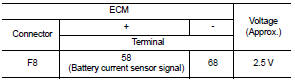

Before measuring the terminal voltage, confirm that the battery is fully charged. Refer to PG-111, "How to Handle Battery".
Is the inspection result normal? YES >> INSPECTION END
NO >> Replace battery negative cable assembly. Refer to PG-125, "Exploded View".
 P1226 TP sensor
DTC Logic
DTC DETECTION LOGIC
DTC CONFIRMATION PROCEDURE
1.PRECONDITIONING
If DTC Confirmation Procedure has been previously conducted, always turn
ignition switch OFF and wait at
least 10 se ...
 P1551, P1552 battery current sensor
DTC Logic
DTC DETECTION LOGIC
DTC CONFIRMATION PROCEDURE
1.PRECONDITIONING
If DTC Confirmation Procedure has been previously conducted, always perform
the following before conducting
the next ...
Other materials:
B1179 lap Pre-tensioner RH
DTC Logic
DTC CONFIRMATION PROCEDURE
1.CHECK SELF-DIAGNOSTIC RESULT
With CONSULT-III
1. Turn ignition switch ON.
2. Perform “Self Diagnostic Result” mode of “AIR BAG” using CONSULT-III.
Without CONSULT-III
1. Turn ignition switch ON.
2. Check the air bag warning lamp status. Refer to SRC ...
Precaution
Precaution for Supplemental Restraint System (SRS) "AIR BAG" and "SEAT
BELT
PRE-TENSIONER"
The Supplemental Restraint System such as “AIR BAG” and “SEAT BELT PRE-TENSIONER”,
used along
with a front seat belt, helps to reduce the risk or severity of injury to the
driver a ...
Transverse link
Exploded View
1. Front suspension member
2. Transverse link
: Always replace after every
disassembly.
: N·m (kg-m, ft-lb)
Removal and Installation
REMOVAL
1. Remove tires. Refer to WT-7, "Removal and Installation".
2. Remove transverse link from steering knuckle.
• MR16DDT: ...