Nissan Juke Service and Repair Manual : Fuel tank
Exploded View

1. Fuel tank cap
2. Grommet
3. Fuel filler tube
4. Clamp
5. Fuel filler hose
6. Clamp
7. Vent hose
8. Fuel tank
9. Mounting band (RH)
10. Mounting band (LH)
 : N·m (kg-m, ft-lb)
Removal and Installation
WARNING:
Be sure to read “General Precautions” when working on the fuel system. Refer to
FL-45, "General Precautions".
REMOVAL
• Drain fuel from fuel tank if necessary. Refer to FL-51, "Removal and Installation".
• Perform work on level place.
1. Remove RH rear wheel.
2. Perform steps 1 to 7 of FL-51, "Exploded View" in “FUEL LEVEL SENSOR UNIT”.
3. Remove center muffler. Refer to EX-17, "Exploded View".
4. Remove insulator on vehicle side located above center muffler.
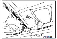
5. Move parking brake cable (1) from the lower face of fuel tank.
Then remove clips for parking brake cable.
6. Disconnect fuel filler hose at fuel tank sid
1 : Filler tube
2 : Vent hose
3 : Filler hose
A : Quick connector
7. Remove vent hose at RH rear wheelwell side.

8. Support the center part of fuel tank (1) with transmission jack (A).
CAUTION:
Securely support the fuel tank with a piece of wood (B)
.

9. Remove fuel tank mounting bands (RH/LH).
10. Lower transmission jack carefully to remove fuel tank while holding it by hand.
CAUTION:
Fuel tank may be in an unstable condition because of the shape of fuel tank
bottom. Never rely on
jack too much. Be sure to hold tank securely.
INSTALLATION
Note the following, and install in the reverse order of removal.
Fuel Tank
1. Temporarily tighten bolts [except (2)] in numerical order as
shown in the figure.
A : Under view
 : Vehicle front
2. Tighten bolt (2) to specified torque, pressing fuel tank in the
direction ( ) shown in the
figure.
3. Tighten bolts [except (2)] to specified torque in the reverse order as shown in the figure.

Fuel Filler Hose
• Surely clamp fuel hose insert fuel filler hose to the length below.
Fuel filler hose : 35 mm (1.38 in) The other hose : 25 mm (0.98 in)
• Be sure hose clamp is not placed on swelled area of fuel filler tube.
• Install fuel filler hose to fuel tank, paying attention to install mark.
Marking faces downward.

• Tighten fuel filler hose clamp so that the remaining length of screw thread becomes to the following.
Fuel filler tube side : 8 - 12 mm (0.28 - 0.43 in) Fuel tank side : 5 - 9 mm (0.25 - 0.35 in)
Vent Tube
1. Check connections for damage or foreign material.
2. Align the matching side connection part with the center of shaft, and insert connector straight until it clicks.
3. After connecting, pull out quick connector and centralized under floor piping by hand. Check connections are secure.
A : Pull

Inspection
INSPECTION AFTER INSTALLATION
Make sure there is no fuel leakage at connections in the following procedure.
• Start engine, rev it up and make sure there is no fuel leakage at connections.
 Fuel level sensor unit
Exploded View
1. Lock ring
2. Fuel level sensor unit
3. Seal packing
A. To fuel tank
: Always replace after every
disassembly
Removal and Installation
WARNING:
Read “General Precautions” ...
 Service data and specifications (SDS)
Fuel tank
...
Other materials:
Engine stand setting
Preparing the engine to be on the stand
Before the engine is mounted on the engine sub-attachment, the engine's
electrical harness must be removed
and the engine oil drained.
1. Remove the multifunction support.
2. Remove the coolant inlet pipe on the water pump.
3. Place the rods (A), ...
Operation inspection
Work Procedure
The purpose of the operational check is to check that the individual system
operates normally.
Check condition : Engine running at normal operating temperature.
1.CHECK BLOWER MOTOR
1. Operate fan control dial.
2. Check that fan speed changes. Check operation for all fan speeds ...
Fan control amplifier
Exploded View
1. A/C unit assembly
2. Fan control amp.*1
3. Blower fan resistor*2
4. Blower motor
5. Blower motor cover
• *1: Automatic air conditioner
• *2: Manual air conditioner
Removal and Installation
REMOVAL
1. Remove instrument panel assembly. Refer to IP-13, "Removal and ...