Nissan Juke Service and Repair Manual : B2614 ACC relay circuit
DTC Logic
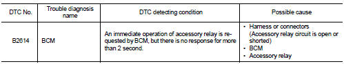
DTC DETECTION LOGIC
DTC CONFIRMATION PROCEDURE
1.PERFORM DTC CONFIRMATION PROCEDURE
1. Turn the power supply position to ACC under the following conditions, and wait for 2 second or more.
CVT models
- Selector lever is in the P or N position
- Do not depress brake pedal
M/T models
- Do not depress clutch pedal
2. Check “Self-diagnosis result” of BCM with CONSULT-III.
Is DTC detected? YES >> Go to PCS-91, "Diagnosis Procedure".
NO >> INSPECTION END
Diagnosis Procedure
1.CHECK ACCESSORY RELAY POWER SUPPLY-1
1. Turn ignition switch OFF.
2. Disconnect accessory relay.
3. Check voltage between accessory relay harness connector and ground.

Is the inspection result normal? YES >> GO TO 3.
NO >> GO TO 2.
2.CHECK ACCESSORY RELAY POWER SUPPLY CIRCUIT
1. Turn ignition switch OFF.
2. Disconnect BCM connector.
3. Check continuity between accessory relay harness connector and BCM harness connector.

4. Check continuity between accessory relay harness connector and ground.

Is the inspection result normal? YES >> Replace BCM. Refer to BCS-93, "Removal and Installation".
NO >> Repair or replace harness.
3.CHECK ACCESSORY RELAY GROUND CIRCUIT
1. Turn ignition switch OFF.
2. Check continuity between accessory relay harness connector and ground.

Is the inspection result normal? YES >> GO TO 4.
NO >> Repair accessory relay ground circuit.
4.CHECK ACCESSORY RELAY POWER SUPPLY CIRCUIT-2
1. Turn ignition switch ACC.
2. Check voltage between accessory relay harness connector and ground.

Is the inspection result normal? YES >> GO TO 5.
NO >> Check continuity open or short between accessory relay and battery.
5.CHECK ACCESSORY RELAY
Refer to PCS-92, "Component Inspection".
Is the inspection result normal? YES >> GO TO 6.
NO >> Replace accessory relay.
6.CHECK INTERMITTENT INCIDENT
Refer to GI-42, "Intermittent Incident".
>> INSPECTION END
Component Inspection
1.CHECK ACCESSORY RELAY
1. Turn ignition switch OFF.
2. Remove accessory relay.
3. Check the continuity between accessory relay terminals.

Is the inspection result normal? YES >> INSPECTION END
NO >> Replace accessory relay


 B2615 blower relay circuit
DTC Logic
DTC DETECTION LOGIC
DTC CONFIRMATION PROCEDURE
1.PERFORM DTC CONFIRMATION PROCEDURE
1. Turn ignition switch ON under the following conditions, and wait for 1
second or more.
CVT m ...
Other materials:
Front door lock
Exploded View
1. Door key cylinder assembly (driver
side)
Outside handle escutcheon (passenger
side)
2. Outside handle
3. Front gasket
4. Inside handle
5. TORX bolt
6. Door lock assembly
7. Key rod (driver side)
8. Outside handle bracket
9. Rear gasket
10. Key rod protector (driv ...
Back door opener actuator
Component Function Check
1.CHECK FUNCTION
1. Select “INTELLIGENT KEY” of “BCM” using CONSULT-III.
2. Select “TRUNK/BACK DOOR” in “ACTIVE TEST” mode.
3. Check that the function operates normally according to the following
conditions.
Is the inspection result normal?
YES >> Back door o ...
Turbocharger
Exploded View
1. Heat insulator
2. Actuator hose
3. Clamp
4. Turbocharger inlet tube
5. Gasket
6. Gasket
7. Clamp
8. Oil outlet hose
9. Oil return pipe
10. Oil supply tube
11. O-ring
12. O-ring
13. Turbocharger
14. Eye bolt
15. Gasket
16. Oil supply tube
A. To EVAP canis ...