Nissan Juke Service and Repair Manual : Wheel alignment
Inspection
DESCRIPTION
Measure wheel alignment under unladen conditions.
NOTE
:
“Unladen conditions” means that fuel, engine coolant, and lubricant are full.
Spare tire, jack, hand tools and
mats are in designated positions.
PRELIMINARY CHECK
Check the following:
• Tires for improper air pressure and wear
• Road wheels for runout: refer to WT-7, "Inspection".
• Wheel bearing axial end play: refer to RAX-4, "Inspection".
• Shock absorber operation
• Each mounting point of axle and suspension for looseness and deformation
• Each of rear suspension beam and shock absorber for cracks, deformation, and
other damage
• Vehicle height (posture)
CAMBER
• Measure camber of both right and left wheels with a suitable alignment gauge.
• If camber is outside specified range, replace rear suspension beam. Refer to RSU-13, "Exploded View".
Camber : Refer to RSU-15, "Wheel Alignment".

TOE-IN
Measure toe-in by the following procedure.
WARNING:
• Always perform the following procedure on a flat surface.
• Check that no person is in front of vehicle before pushing it.
1. Bounce the front of vehicle up and down to stabilize the vehicle height (posture).
2. Push vehicle straight ahead about 5 m (16 ft).
3. Put matching mark (A) on base line of the tread (rear side) of both tires at the same height of hub center. These are measuring points.
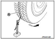
4. Measure distance (A) (rear side).
: Vehicle front
5. Push vehicle slowly ahead to rotate wheels 180 degrees (1/2 turn).
NOTE
:
If the wheels rotates more than 180 degrees (1/2 turn), start this
procedure again from the beginning. Do not push the vehicle
backward.
6. Measure distance (B) (front side).

Total toe-in = A − B Total toe-in : Refer to RSU-15, "Wheel Alignment".
• If toe-in is outside specified range, replace rear suspension beam. Refer to RSU-13, "Exploded View".
 Rear suspension assembly
Inspection
COMPONENT PART
Check the mounting conditions (looseness, backlash) of each component and
component conditions (wear,
damage) are normal.
SHOCK ABSORBER ASSEMBLY
Check for oil leaka ...

Other materials:
Instrument panel assembly
Exploded View
LHD models
1. Front passenger air bag module
2. Instrument panel assembly
3. Instrument side finisher LH
4. Combination meter
5. Cluster lid A
6. Push-button ignition switch
7. Steering column upper cover
8. Steering lock escutcheon
9. Steering column lower cover
10. ...
Component parts
Component Parts Location
LHD models
1. Multi display unit*
Refer to DMS-3, "Component Parts
Location".
2. ABS actuator and electric unit (control
unit)
Refer to BRC-9, "Component Parts
Location" (without ESP), BRC-97,
"Component Parts Location" (with
ESP).
...
Electric controlled coupling oil seal
Exploded View
1. Rear final drive assembly
2. Electric controlled coupling oil seal
A. Oil seal lip
: Vehicle front
: Always replace after every
disassembly.
: Apply multi purpose grease
: Apply gear oil.
Removal and Installation
REMOVAL
1. Remove rear drive shafts. Refer to RAX-17, & ...