Nissan Juke Service and Repair Manual : U0101 Can comm circuit
Description
CAN (Controller Area Network) is a serial communication line for real time application. It is an on-vehicle multiplex communication line with high data communication speed and excellent error detection ability. Many electronic control units are equipped onto a vehicle, and each control unit shares information and links with other control units during operation (not independent). In CAN communication, control units are connected with 2 communication lines (CAN H line, CAN L line) allowing a high rate of information transmission with less wiring.
Each control unit transmits/receives data but selectively reads required data only.
DTC Logic
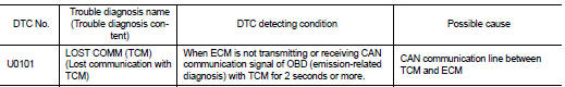
DTC DETECTION LOGIC
DTC CONFIRMATION PROCEDURE
1.PERFORM DTC CONFIRMATION PROCEDURE
1. Turn ignition switch ON and wait at least 3 seconds.
2. Check DTC.
Is DTC detected? YES >> Proceed to EC-159, "Diagnosis Procedure".
NO >> INSPECTION END
Diagnosis Procedure
Perform the trouble diagnosis for CAN communication system. Refer to LAN-17, "Trouble Diagnosis Flow Chart".
 Power supply and ground circuit
Diagnosis Procedure
1.CHECK FUSE
Is the fuse fusing?
YES >> Replace the fuse after repairing the applicable circuit.
NO >> GO TO 2.
2.CHECK GROUND CONNECTION
1. Turn ignition swi ...
 U0122 Vehicle dynamics control
module
U0122 Vehicle dynamics control
module
Description
CAN (Controller Area Network) is a serial communication line for real time
application. It is an on-vehicle multiplex
communication line with high data communication speed and excelle ...
Other materials:
Ecu diagnosis information
BCM
Reference Value
VALUES ON THE DIAGNOSIS TOOL
CONSULT-III MONITOR ITEM
TERMINAL LAYOUT
PHYSICAL VALUES
• *1: With manual A/C
• *2: RHD models
• *3: M/T models
• *4: LHD models
• *5: Except M/T models
Fail-safe
FAIL-SAFE CONTROL BY DTC
B ...
Back-up lamp switch : Component Inspection
1.CHECK BACK-UP LAMP SWITCH
1. Disconnect position switch connector. Refer to TM-77, "Removal and
Installation".
2. Check continuity between position switch terminals.
Is the inspection result normal?
YES >> INSPECTION END
NO >> Replace position switch. Refer to TM-7 ...
Tire labeling
Federal law requires tire manufacturers to place standardized information on
the sidewall of all tires. This information identifies and describes the fundamental
characteristics of the tire and also provides the tire identification number (TIN)
for safety standard certification. The TIN can be ...