Nissan Juke Service and Repair Manual : Ecu diagnosis information
BCM
Reference Value
VALUES ON THE DIAGNOSIS TOOL
CONSULT-III MONITOR ITEM


TERMINAL LAYOUT

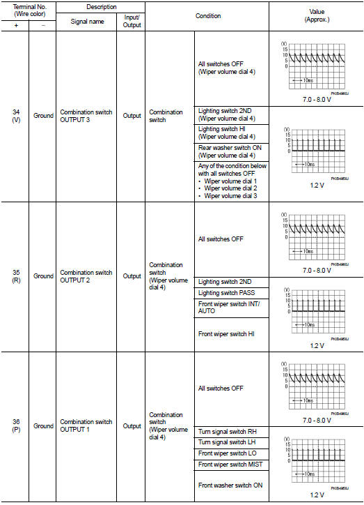
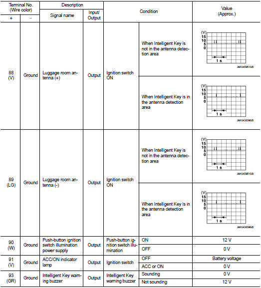
PHYSICAL VALUES


• *1: With manual A/C
• *2: RHD models
• *3: M/T models
• *4: LHD models
• *5: Except M/T models
Fail-safe
FAIL-SAFE CONTROL BY DTC
BCM performs fail-safe control when any DTC are detected.


REAR WIPER MOTOR PROTECTION
BCM detects the rear wiper stopping position according to the rear wiper stop position signal.
When the rear wiper stop position signal does not change for more than 5 seconds while driving the rear wiper, BCM stops power supply to protect the rear wiper motor.
Condition of cancellation 1. More than 1 minute is passed after the rear wiper stop.
2. Turn rear wiper switch OFF.
3. Operate the rear wiper switch or rear washer switch.
FAIL-SAFE CONTROL BY LIGHT AND RAIN SENSOR MALFUNCTION
BCM detects the light and rain sensor serial link error and the light and rain sensor malfunction.
BCM controls the following fail-safe when light and rain sensor has a malfunction.
Fail-safe Control
• Auto light control: Headlamp low beam, parking lamp, license plate lamp and
tail lamp are turned ON.
• Front wiper control
- Front wiper switch AUTO and sensing rain drop: The condition just before the
activation of fail-safe is maintained
until the front wiper switch is turned OFF.
- Front wiper switch AUTO and not sensing rain drop: Front wiper is LO operation until the front wiper switch is turned off.
FAIL-SAFE CONTROL OF COMBINATION SWITCH READING FUNCTION CAUSED BY LOW POWER SUPPLY VOLTAGE
If voltage of battery power supply lower, BCM maintains combination switch reading to the status when input voltage is less than approximately 9 V.
NOTE
:
When voltage of battery power supply is approximately 9 V or more, combination
switch reading function
returns to normal operation
DTC Inspection Priority Chart
If some DTCs are displayed at the same time, perform inspections one by one based on the following priority chart.


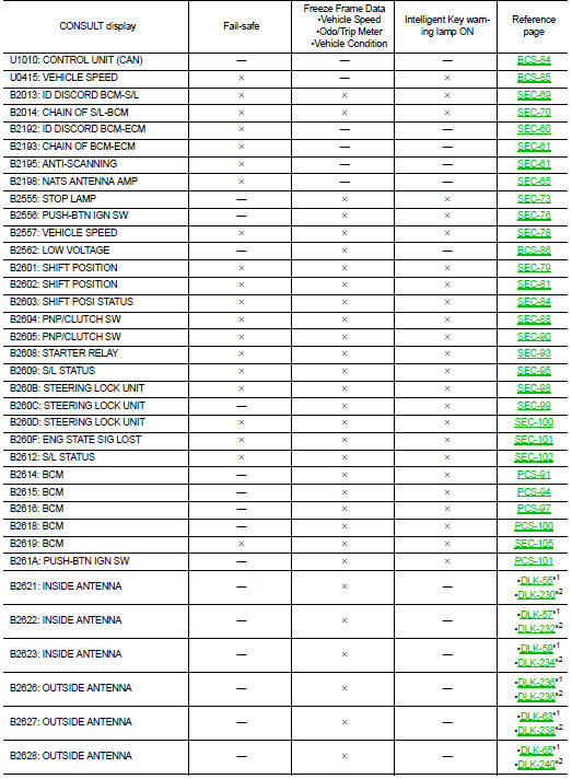
DTC Index
NOTE
:
The details of time display are as follows.
• CRNT: A malfunction is detected now.
• PAST: A malfunction was detected in the past.
IGN counter is displayed on Freeze Frame Data. For details of Freeze Frame Data, refer to BCS-17, "COMMON ITEM : CONSULT-III Function (BCM - COMMON ITEM)".


NOTE
:
• *1: With super lock
• *2: Without super lock
 Diagnosis system (BCM)
Common item
COMMON ITEM : CONSULT-III Function (BCM - COMMON ITEM)
APPLICATION ITEM
CONSULT-III performs the following functions via CAN communication with BCM.
SYSTEM APPLICATION
BCM can perfo ...
 Wiring diagram
BCM
LHD
LHD : Wiring Diagram
For connector terminal arrangements, harness layouts, and alphabets in a
(option abbreviation; if not
described in wiring diagram), refer to GI-12, "Connector I ...
Other materials:
On Board Diagnostic (OBD) System of Engine and CVT
The ECM has an on board diagnostic system. It will light up the malfunction
indicator lamp (MIL) to warn the
driver of a malfunction causing emission deterioration.
CAUTION:
• Be sure to turn the ignition switch OFF and disconnect the negative battery
cable before any repair
or inspection ...
Inspection
INSPECTION AFTER INSTALLATION
• Check accelerator pedal moves smoothly within the whole operation range
when it is fully depressed and
released.
• Check accelerator pedal securely returns to the fully released position.
• For the electrical inspection of accelerator pedal position sensor. Refe ...
P1205 exhaust fuel injector
DTC Logic
DTC DETECTION LOGIC
Diagnosis Procedure
1.CHECK EXHAUST FUEL INJECTOR POWER SUPPLY CIRCUIT FOR OPEN AND SHORT
1. Turn ignition switch OFF.
2. Disconnect exhaust fuel injector harness connector.
3. Turn ignition switch ON.
4. Check the voltage between exhaust fuel injector harness ...