Nissan Juke Service and Repair Manual : System
System Description
Fan speed of blower motor is changed by the combination of fan control dial (fan switch) operation and blower fan resistor control.
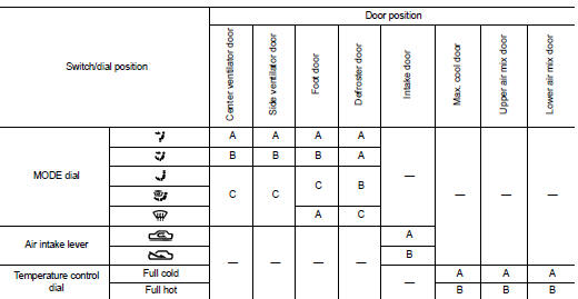
Door Control
SWITCHES AND THEIR CONTROL FUNCTIONS
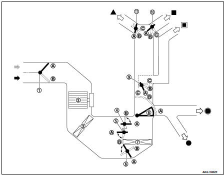
1. Intake door
2. Blower motor
3. Air conditioner filter
4. Max. cool door
5. Upper air mix door
6. Lower air mix door
7. Heater core
8. Foot door
9. Side ventilator door
10. Center ventilator door
11. Defroster door
 Fresh air intake
 Recirculation air
 Defroster
 Center ventilator
 Side ventilator
 Foot
Foot
 Rear foot*
*: With rear foot duct
AIR DISTRIBUTION
Without rear foot duct

With rear foot duct

 Component parts
Component Part Location
1. BCM
Refer to BCS-161, "Removal and Installation".
2. Heater control
3. Blower fan resistor
4. Blower motor
A. Left side of heater unit assembly
B. Right ...
 Operation
Switch Name and Function
HEATER CONTROLLER (HEATER CONTROL)
1. MODE dial
2. Fan control dial
3. Temperature control dial
4. Intake lever
...
Other materials:
P0087 fuel pump
DTC Logic
DTC DETECTION LOGIC
NOTE:
• Conditions for applying the diagnostic procedure to the stored DTCs:
The DTC becomes present during the first 30 seconds after the engine starts.
• In low ambient temperature conditions, diagnostic cannot make difference
between a normal long engine
st ...
Auto door lock operation does not operate
Diagnosis Procedure
1.CHECK “AUTO LOCK SET” SETTING WITH CONSULT-III
1. Select “MULTI REMOTE ENT” of “BCM” using CONSULT-III.
2. Select “AUTO LOCK SET” in “WORK SUPPORT” mode.
3. Check “AUTO LOCK SET” in “WORK SUPPORT”.
Refer to DLK-372, "MULTI REMOTE ENT : CONSULT-III Function (BCM - MU ...
Keyfob
Replace the battery in the keyfob as follows:
1. Remove the screw.
2. Insert a small screwdriver into the slit of the corner and twist it to separate
the upper part from the lower part. Use a cloth to protect the casing.
3. Replace the battery with a new one.
Recommended battery:
CR1620 or eq ...