Nissan Juke Service and Repair Manual : Steering switch ground circuit
Description
Transmits the steering switch signal to NAVI control unit.
Diagnosis Procedure
1.CHECK STEERING SWITCH SIGNAL GROUND CIRCUIT
1. Disconnect NAVI control unit connector and spiral cable connector.
2. Check continuity between NAVI control unit harness connector and spiral cable harness connector.

Is the inspection result normal? YES >> GO TO 2.
NO >> Repair harness or connector. 2.CHECK SPIRAL CABLE
Check spiral cable.
Is the inspection result normal? YES >> GO TO 3.
NO >> Replace spiral cable. Refer to SR-16, "Exploded View".
3.CHECK GROUND CIRCUIT
1. Connect NAVI control unit connector.
2. Check continuity between NAVI control unit harness connector and ground.
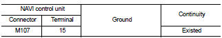
Is the inspection result normal? YES >> GO TO 4.
NO >> Replace NAVI control unit. Refer to AV-84, "Removal and Installation".
4.CHECK STEERING SWITCH
1. Turn ignition switch OFF.
2. Check steering switch. Refer to AV-75, "Component Inspection".
Is the inspection result normal? YES >> INSPECTION END
NO >> Replace steering switch. Refer to AV-91, "Exploded View".
Component Inspection
Measure the resistance between the steering switch connector.

Standard

 Steering switch signal B circuit
Description
Transmits the steering switch signal to NAVI control unit.
Diagnosis Procedure
1.CHECK STEERING SWITCH SIGNAL B CIRCUIT
1. Disconnect NAVI control unit connector and spiral cable conne ...

Other materials:
C1166, C1167 SV system
DTC Logic
DTC DETECTION LOGIC
DTC CONFIRMATION PROCEDURE
1.PRECONDITIONING
If “DTC CONFIRMATION PROCEDURE” has been previously conducted, always turn
ignition switch OFF and
wait at least 10 seconds before conducting the next test.
>> GO TO 2.
2.CHECK DTC DETECTION
With CONSULT ...
U1000, U1001 CAN COMM CIRCUIT
Description
CAN (Controller Area Network) is a serial communication line for real time
application. It is an on-vehicle multiplex
communication line with high data communication speed and excellent error
detection ability. Many electronic
control units are equipped onto a vehicle, and each co ...
System
AUTO RETRACTABLE DOOR MIRORR FUNCTION
AUTO RETRACTABLE DOOR MIRORR FUNCTION : System Diagram
AUTO RETRACTABLE DOOR MIRORR FUNCTION : System Description
BCM retracts door mirror when door lock signal is received from Intelligent
Key or door request switch.
OPERATION CONDITION
The system oper ...