Nissan Juke Service and Repair Manual : Radiator core support
HR16DE
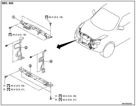
HR16DE : Exploded View

1. Radiator core support upper
2. Air guide RH (MT models)
3. Radiator core support lower
4. Air guide LH
5. Air guide (upper)
6. Air guide LH (CVT models)
7. Air guide RH (CVT models)
 : N·m (kg-m, ft-lb)
HR16DE : Removal and Installation
RADIATOR CORE SUPPORT UPPER
Removal
1. Remove front bumper fascia. Refer to EXT-13, "Removal and Installation".
2. Remove front combination lamp (LH and RH). Refer to EXL-91, "Removal and Installation".
3. Remove headlamp (LH and RH). Refer to EXL-89, "Removal and Installation".
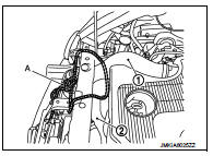
4. Disconnect crash zone sensor harness connector. Refer to SR-26, "Removal and Installation".
CAUTION:
Turn ignition switch OFF, disconnect battery negative terminal and then wait for
at least 3 minutes.
5. Remove hood lock and hood lock cable fixing clip. Refer to DLK-470, "HOOD LOCK : Removal and Installation".
6. Remove horn bracket. Refer to HRN-4, "Removal and Installation".
7. Remove air guide (upper) fixing clips, and then remove air guide (upper).
8. Remove upper fixing clips (2) of air guide (LH and RH) (1).

9. Remove hood support rod. Refer to DLK-444, "HOOD SUPPORT ROD : Removal and Installation".
10. Remove mounting bolts, and then remove radiator core support upper.
Installation Install in the reverse order of removal.
RADIATOR CORE SUPPORT LOWER
Removal
1. Remove front bumper fascia. Refer to EXT-13, "Removal and Installation".
2. Remove lower fixing clips (2) of radiator side seal (LH and RH) (1).

3. Use belts (A) to suspend radiator and condenser to prevent them from falling.
CAUTION:
Never damage radiator and condenser.

4. Remove mounting bolts, and then remove radiator core support lower.
Installation
Install in the reverse order of removal.
MR16DDT
MR16DDT : Exploded View
1. Radiator core support upper
2. Air guide RH
3. Radiator core support lower
4. Air guide LH
A : 2WD models
B : 4WD models
 : N·m (kg-m, ft-lb)
MR16DDT : Removal and Installation
RADIATOR CORE SUPPORT UPPER
Removal
1. Remove front bumper fascia. Refer to EXT-13, "Removal and Installation".
2. Remove front combination lamp (LH and RH). Refer to EXL-91, "Removal and Installation".
3. Remove headlamp (LH and RH). Refer to EXL-89, "Removal and Installation".
4. Disconnect crash zone sensor harness connector. Refer to SR-26, "Removal and Installation".
CAUTION:
Turn ignition switch OFF, disconnect battery negative terminal and then wait for
at least 3 minutes.
5. Remove hood lock and hood lock cable fixing clip. Refer to DLK-470, "HOOD LOCK : Removal and Installation".
6. Remove horn bracket. Refer to HRN-4, "Removal and Installation".
7. Remove upper fixing clips (2) of air guide (LH and RH) (1).

8. Remove hood support rod. Refer to DLK-444, "HOOD SUPPORT ROD : Removal and Installation".
9. Remove mounting bolts, and then remove radiator core support upper.
Installation Install in the reverse order of removal.
RADIATOR CORE SUPPORT LOWER
Removal
1. Remove front bumper fascia. Refer to EXT-13, "Removal and Installation".
2. Remove lower fixing clips (2) of radiator side seal (LH and RH) (1).

3. Using strings (A), hang inlet hose (1) and inlet hose (2) together with charge air cooler.
CAUTION:
Never damage inlet hoses with charge air cooler.
4. Support lower side radiator using wooden blocks (B) and a floor jack (A).
CAUTION:
Never damage radiator.

5. Remove mounting bolts, and then remove radiator core support lower.
Installation
Install in the reverse order of removal.
 Hood
Hood
Exploded View
1. Hood assembly
2. Hood bumper rubber
3. Radiator core seal
4. Hood bumper rubber
5. Clamp
6. Hood hinge
7. Grommet
8. Hood support rod
: Clip
: Pawl
: Body grease
Ho ...
 Front fender
Exploded View
1. Front fender assembly
2. Front fender stiffener
: Vehicle front
Removal and Installation
REMOVAL
1. Remove front fillet molding. Refer to EXT-26, "FRONT FILLET MOLDING : ...
Other materials:
P0234 TC system
DTC Logic
DTC DETECTION LOGIC
NOTE:
If DTC P0234 is displayed with DTC P0237 or P0238, first perform the trouble
diagnosis for DTC P0237 or
P0238. Refer to EC-260, "DTC Logic".
DTC CONFIRMATION PROCEDURE
1.PERFORM COMPONENT FUNCTION CHECK
Perform component function check. Refer ...
Engine maintenance (HR16DE)
Drive belt
DRIVE BELT : Checking
• Inspection should be done only when engine is cold or over 30
minutes after the engine is stopped.
1 : Alternator
2 : Water pump
3 : Crankshaft pulley
4 : A/C compressor
5 : Idler pulley
6 : Drive belt
• Visually check belts for wear, damage, and cracks ...
P0107, P0108 atmospheric pressure
sensor
DTC Logic
DTC DETECTION LOGIC
DTC CONFIRMATION PROCEDURE
1.PRECONDITIONING
If DTC Confirmation Procedure has been previously conducted, always perform
the following procedure
before conducting the next test.
1. Turn ignition switch OFF and wait at least 10 seconds.
2. Turn ignition swi ...