Nissan Juke Service and Repair Manual : Push-button ignition switch position indicator
Description
Push-button ignition switch changes the power supply position.
BCM maintains the power supply position status.
BCM changes the power supply position with the operation of the push-button ignition switch.
Component Function Check
1.CHECK FUNCTION
Check push-button ignition switch (“PUSH SWITCH INDICATOR”) in Active Test Mode with CONSULT-III.

Is the inspection result normal? YES >> INSPECTION END
NO >> Refer to PCS-111, "Diagnosis Procedure".
Diagnosis Procedure
1.CHECK PUSH-BUTTON IGNITION SWITCH INPUT SIGNAL
1. Turn ignition switch OFF.
2. Disconnect push-button ignition switch connector.
3. Check voltage between push-button ignition switch harness connector and ground.

Is the inspection normal? YES >> GO TO 2.
NO-1 >> Check 10 A fuse [No.13, located in fuse block (J/B)].
NO-2 >> Check harness for open or short between push-button ignition switch and fuse.
2.CHECK BCM INPUT
1. Connect push-button ignition switch connector.
2. Disconnect BCM connector.
3. Check voltage between BCM connector and ground.

Is the inspection normal? YES >> Replace BCM. Refer to BCS-93, "Removal and Installation".
NO >> GO TO 3.
3.CHECK PUSH-BUTTON IGNITION SWITCH CIRCUIT
1. Disconnect push-button ignition switch connector.
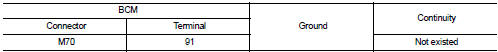
2. Check continuity between BCM harness connector and push-button ignition switch harness connector.

3. Check continuity between BCM harness connector and ground.
Is the inspection normal? YES >> Replace push-button ignition switch.
NO >> Repair or replace harness.
 Push-button ignition switch
Component Function Check
1.CHECK FUNCTION
1. Select “PUSH SW” in “Data Monitor” mode with CONSULT-III.
2. Check the push-button ignition switch signal under the following conditions.
Is the indi ...

Other materials:
B1129 side air bag module RH
DTC Logic
DTC DETECTION LOGIC
DTC CONFIRMATION PROCEDURE
1.CHECK SELF-DIAG RESULT
With CONSULT-III
1. Turn ignition switch ON.
2. Perform “Self Diagnostic Result” mode of “AIR BAG” using CONSULT-III.
Without CONSULT-III
1. Turn ignition switch ON.
2. Check the air bag warning lamp statu ...
Removal and Installation
REMOVAL
1. Separate the rear propeller shaft. Refer to DLN-121, "Removal and
Installation".
2. Remove right side drive shaft. Refer to FAX-24, "RIGHT SIDE : Removal and
Installation".
3. Remove catalyst convertor support bracket (RH). EM-35, "4WD : Removal and
Insta ...
B26F8 BCM
DTC Logic
DTC DETECTION LOGIC
NOTE:
DTC B26F8 can be detected even though the related circuit is not used in this
vehicle.
DTC CONFIRMATION PROCEDURE
1.PERFORM DTC CONFIRMATION PROCEDURE
1. Turn ignition switch ON and wait 1 second.
2. Check DTC in “Self Diagnostic Result” mode of “BCM” u ...