Nissan Juke Service and Repair Manual : Removal and Installation
REMOVAL
1. Separate the rear propeller shaft. Refer to DLN-121, "Removal and Installation".
2. Remove right side drive shaft. Refer to FAX-24, "RIGHT SIDE : Removal and Installation".
3. Remove catalyst convertor support bracket (RH). EM-35, "4WD : Removal and Installation".
4. Remove heat insulator (1).
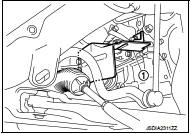
5. Remove transfer gusset (1).
6. Remove catalyst convertor upport bracket rear. EM-59, "4WD : Removal and Installation".
7. Remove rear torque rod and rear torque rod bracket. Refer to EM-59, "4WD : Removal and Installation".
8. Remove the mounting bolts of transaxle assembly and transfer assembly.

9. Remove transfer assembly from the vehicle.
 : Vehicle front
CAUTION:
Never damage ring gear shaft.

INSTALLATION
Note the following, and install in the reverse order of removal.
• When installing the transfer to the transaxle, install the mounting bolts following the standard below.


CAUTION:
• When installing transfer assembly to transaxle assembly,
replace the side oil seal (transfer joint). Refer to TM-292,
"Removal and Installation".
• Never damage side oil seal (the joint part of transfer).
• When installing heat insulator (1), install the mounting bolts and nut following procedure.


• Check oil level and check for oil leakage after installation. Refer to DLN-90, "Inspection".
 Exploded View
1. Transfer gusset
2. Transfer assembly
3. Heat insulator
: Vehicle front
: N·m (kg-m, ft-lb)
...

Other materials:
Off position warning does not operate
Diagnosis Procedure
1.CHECK DTC WITH BCM AND COMBINATION METER
Check that DTC is not detected with BCM and combination meter.
Is the inspection result normal?
YES >> GO TO 2.
NO-1 >> Refer to BCS-67, "DTC Index". (BCM)
NO-2 >> Refer to MWI-36, "DTC Index&qu ...
RearView monitor (if so equipped)
When the shift lever is shifted into the R (Reverse) position, the monitor display
shows the view to the rear of the vehicle.
The system is designed as an aid to the driver in situations such as slot parking
or parallel parking.
WARNING
Failure to follow the warnings and instructions for prop ...
Cleaning interior
Occasionally remove loose dust from the interior trim, plastic parts and seats
using a vacuum cleaner or soft bristled brush. Wipe the vinyl and leather surfaces
with a clean, soft cloth dampened in mild soap solution, then wipe clean with a
dry soft cloth.
Regular care and cleaning is requir ...