Nissan Juke Service and Repair Manual : Power supply and ground circuit
Diagnosis Procedure
1.CHECK GROUND CONNECTION
1. Turn ignition switch OFF.
2. Check ground connection E21 and E38. Refer to Ground Inspection in GI-44, "Circuit Inspection".
Is the inspection result normal? YES >> GO TO 2.
NO >> Repair or replace ground connection.
2.CHECK ECM GROUND CIRCUIT FOR OPEN AND SHORT
1. Disconnect ECM harness connectors.
2. Check the continuity between ECM harness connector and ground.

3. Also check harness for short to power.
Is the inspection result normal? YES >> GO TO 4.
NO >> GO TO 3.
3.DETECT MALFUNCTIONING PART
Check the following.
• Harness connectors E8, F1 • Harness for open or short between ECM and ground
>> Repair open circuit or short to power in harness or connectors.
4.CHECK ECM POWER SUPPLY CIRCUIT-I
1. Reconnect ECM harness connectors.
2. Turn ignition switch ON.
3. Check the voltage between ECM harness connector and ground.

Is the inspection result normal? YES >> GO TO 6.
NO >> GO TO 5.
5.DETECT MALFUNCTIONING PART
Check the following.
• 15 A fuse (No. 62)
• Harness for open or short between ECM and fuse
>> Repair open circuit or short to ground or short to power in harness or connectors.
6.CHECK ECM POWER SUPPLY CIRCUIT-II
1. Turn ignition switch OFF and wait at least 10 seconds.
2. Turn ignition switch ON and then OFF.
Check the voltage between ECM harness connector and ground.

Is the inspection result normal? YES >> GO TO 7.
NO >> GO TO 9.
7.CHECK ECM POWER SUPPLY CIRCUIT-III
1. Turn ignition switch ON.
2. Check the voltage between IPDM E/R harness connector and ground.

Is the inspection result normal? YES >> GO TO 8.
NO >> Replace IPDM E/R.
8.CHECK INTERMITTENT INCIDENT
Refer to GI-42, "Intermittent Incident".
>> INSPECTION END
9.CHECK ECM POWER SUPPLY CIRCUIT-IV
1. Turn ignition switch OFF and wait at least 10 seconds.
2. Check the voltage between ECM harness connector and ground.

Is the inspection result normal? YES >> GO TO 13.
NO >> GO TO 10.
10.CHECK ECM POWER SUPPLY CIRCUIT-V
1. Disconnect ECM harness connector.
2. Disconnect IPDM E/R harness connector E14.
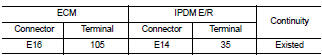
3. Check the continuity between ECM harness connector and IPDM E/R harness connector.

4. Also check harness for short to ground and short to power.
Is the inspection result normal? YES >> GO TO 12.
NO >> GO TO 11.
11.DETECT MALFUNCTIONING PART
Check the following.
• Harness connectors E8, F1 • Harness for open or short between ECM and IPDM E/R
>> Repair open circuit or short to ground or short to power in harness or connectors.
12.CHECK 20 A FUSE
1. Disconnect 20 A fuse (No. 43) from IPDM E/R.
2. Check 20 A fuse.
Is the inspection result normal? YES >> GO TO 14.
NO >> Replace 20 A fuse.
13.CHECK ECM POWER SUPPLY CIRCUIT-VI
1. Disconnect ECM harness connector.
2. Disconnect IPDM E/R harness connector E14.
3. Check the continuity between ECM harness connector and IPDM E/R harness connector.
4. Also check harness for short to ground and short to power.
Is the inspection result normal? YES >> GO TO 14.
NO >> Repair open circuit or short to ground or short power in harness or connectors.
14.CHECK INTERMITTENT INCIDENT
Refer to GI-42, "Intermittent Incident".
Is the inspection result normal? YES >> Replace IPDM E/R.
NO >> Repair or replace harness or connectors.
 Trouble diagnosis - specification valuE
Description
The specification (SP) value indicates the tolerance of the value that is
displayed in “SPEC” of “DATA MONITOR”
mode of CONSULT-III during normal operation of the Engine Control System ...
 U1000, U1001 CAN COMM CIRCUIT
Description
CAN (Controller Area Network) is a serial communication line for real time
application. It is an on-vehicle multiplex
communication line with high data communication speed and excellen ...
Other materials:
Body construction
Body Construction (RHD Models)
1. Outer side body
2. Outer front pillar reinforcement
3. Upper inner front pillar
4. Lower dash
5. Hoodledge reinforcement
6. Lower front pillar hinge brace
7. Weld nut
8. Side dash
9. Upper hinge plate
10. Lower hinge plate
11. Inner front pillar ...
Ambient sensor
Removal and Installation
REMOVAL
1. Remove bumper fascia assembly. Refer to EXT-13, "Removal and
Installation".
2. Disengage fixing pawl, and then remove ambient sensor (1)
from air guide RH.
: Pawl
3. Disconnect ambient sensor connector (2), and then remove
ambient sensor.
INS ...
Additional service when replacing transaxle assembly
Description
Perform the following work after the transaxle assembly is replaced.
Erasing the calibration data
• The TCM acquires calibration data (individual characteristic value) of each
solenoid that is stored in the
ROM assembly (in the control valve). This enables the TCM to perform accu ...