Nissan Juke Service and Repair Manual : Power supply and ground circuit
Combination meter
COMBINATION METER : Diagnosis Procedure
1.CHECK FUSE
Check for blown fuses.

Is the inspection result normal? YES >> GO TO 2.
NO >> Be sure to eliminate cause of malfunction before installing new fuse.
2.CHECK POWER SUPPLY CIRCUIT
Check voltage between combination meter harness connector and ground.
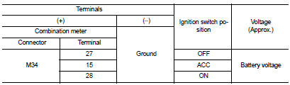
Is the inspection result normal? YES >> GO TO 3.
NO >> Check harness between combination meter and fuse.
3.CHECK GROUND CIRCUIT
1. Turn ignition switch OFF.
2. Disconnect combination meter connector.
3. Check continuity between combination meter harness connector and ground.

Is the inspection result normal? YES >> INSPECTION END
NO >> Repair harness or connector.
 B2321, B2322 oil level sensor
Description
The oil level sensor detects the level of engine oil, and then transmits the
oil level signal to the combination
meter.
DTC Logic
DTC DETECTION LOGIC
NOTE:
When the following con ...
 Fuel level sensor signal circuit
Component Function Check
2WD MODELS
1.CHECK COMBINATION METER OUTPUT SIGNAL
Select the “Data Monitor” for the “METER/M&A” and compare the “FUEL METER”
monitor value with the fuel
gauge readi ...
Other materials:
Off position warning does not operate
Diagnosis Procedure
1.CHECK DTC WITH BCM AND COMBINATION METER
Check that DTC is not detected with BCM and combination meter.
Is the inspection result normal?
YES >> GO TO 2.
NO-1 >> Refer to BCS-67, "DTC Index". (BCM)
NO-2 >> Refer to MWI-36, "DTC Index&qu ...
Service Equipment
RECOVERY/RECYCLING RECHARGING EQUIPMENT
Be certain to follow the manufacturer’s instructions for machine operation
and machine maintenance. Never
introduce any refrigerant other than that specified into the machine.
ELECTRICAL LEAK DETECTOR
Be certain to follow the manufacturer’s instruction ...
Keyfob battery
Exploded View
1. Upper case
2. Key
3. Switch cover
4. Switch rubber
5. Board surface
6. Battery
7. plate
8. Lower case
9. Screw
Removal and Installation
REMOVAL
1. Remove screw (9) on the rear of keyfob.
2. Place the key with the lower case (8) facing up. Set a screw-driver wrap ...