Nissan Juke Service and Repair Manual : Fuel level sensor signal circuit
Component Function Check
2WD MODELS
1.CHECK COMBINATION METER OUTPUT SIGNAL
Select the “Data Monitor” for the “METER/M&A” and compare the “FUEL METER” monitor value with the fuel gauge reading on the combination meter.

Does monitor value match fuel gauge reading? YES >> INSPECTION END
NO >> Replace combination meter. Refer to MWI-69, "Removal and Installation".
4WD MODELS
1.CHECK COMBINATION METER OUTPUT SIGNAL
Select the “Data Monitor” for the “METER/M&A” and compare the “FUEL METER” monitor value with the fuel gauge reading on the combination meter.

Does monitor value match fuel gauge reading? YES >> INSPECTION END
NO >> Replace combination meter. Refer to MWI-69, "Removal and Installation".
Diagnosis Procedure
1.CHECK COMBINATION METER INPUT SIGNAL
1. Turn ignition switch ON.
2. Check voltage between combination meter harness connector and ground.

Does it match fuel gauge reading? YES >> GO TO 2.
NO >> Replace the combination meter. Refer to MWI-69, "Removal and Installation".
2.CHECK FUEL LEVEL SENSOR CIRCUIT
1. Turn ignition switch OFF.
2. Disconnect combination meter connector and fuel level sensor unit connector.
3. Check continuity between combination meter harness connector terminal and fuel level sensor unit harness connector terminal.
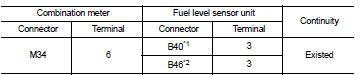
*1: 2WD models
*2: 4WD models
4. Check continuity between combination meter harness connector terminal and ground.
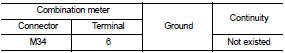
Is the inspection result normal? YES >> GO TO 3.
NO >> Repair harness or connector.
3.CHECK FUEL LEVEL SENSOR GROUND CIRCUIT
Check continuity between fuel level sensor unit harness connector terminal and combination meter harness connector terminal.

*1: 2WD models
*2: 4WD models
Is the inspection result normal? YES >> INSPECTION END
NO >> Repair harness or connector.
Component Inspection
2WD MODELS
1.REMOVE FUEL LEVEL SENSOR UNIT (MAIN)
Remove the fuel level sensor unit (main). Refer to FL-6, "2WD : Removal and Installation" (MR16DDT), FL-33, "Removal and Installation" (HR16DE), or FL-51, "Removal and Installation" (K9K).
>> GO TO 2.
2.CHECK FUEL LEVEL SENSOR UNIT (MAIN)
Check the resistance between fuel level sensor unit and fuel pump.


*: When float rod is contact with stopper.
Is inspection result OK? YES >> INSPECTION END
NO >> Replace the fuel level sensor unit (main). Refer to FL-6, "2WD : Removal and Installation" (MR16DDT), FL-33, "Removal and Installation" (HR16DE), or FL-51, "Removal and Installation" (K9K).
4WD MODELS
1.REMOVE FUEL LEVEL SENSOR UNIT (MAIN)
Remove the fuel level sensor unit (main). Refer to FL-11, "4WD : Removal and Installation".
>> GO TO 2.
2.CHECK FUEL LEVEL SENSOR UNIT (MAIN)
Check the resistance between fuel level sensor unit and fuel pump.


*: When float rod is contact with stopper.
Is inspection result OK? YES >> GO TO 3.
NO >> Replace fuel level sensor unit (main). Refer to FL-11, "4WD : Removal and Installation".
3.REMOVE FUEL LEVEL SENSOR UNIT (SUB)
Remove the fuel level sensor unit (sub). Refer to FL-11, "4WD : Removal and Installation".
>> GO TO 4.
4.CHECK FUEL LEVEL SENSOR UNIT (SUB)
Check the resistance between fuel level sensor unit (sub).


*: When float rod is contact with stopper.
Is inspection result OK? YES >> INSPECTION END
NO >> Replace fuel level sensor unit (sub). Refer to FL-11, "4WD : Removal and Installation".
 Power supply and ground circuit
Combination meter
COMBINATION METER : Diagnosis Procedure
1.CHECK FUSE
Check for blown fuses.
Is the inspection result normal?
YES >> GO TO 2.
NO >> Be sure to eliminate cause of ...
 Oil pressure switch signal circuit
Component Function Check
1.CHECK COMBINATION METER INPUT SIGNAL
Select the “Data Monitor” for the “METER/M&A” and check the “OIL W/L” monitor
value.
“OIL W/L”
Ignition switch ON : On
Engine ...
Other materials:
Diagnosis and repair work flow
Flowchart of Trouble Diagnosis
NOTE:
“DTC” includes DTC at the 1st trip.
1.OBTAIN INFORMATION ABOUT SYMPTOM
1. Refer to TM-372, "Question sheet" and interview the customer to obtain the
malfunction information (conditions
and environment when the malfunction occurred) as much as p ...
B27B0 A/C auto AMP.
DTC Logic
DTC DETECTION LOGIC
NOTE:
• If DTC is displayed along with DTC U1000, first perform the trouble diagnosis
for DTC U1000. Refer to HAC-
141, "DTC Logic".
• If DTC is displayed along with DTC U1010, first perform the trouble diagnosis
for DTC U1010. HAC-142,
"DTC Log ...
B2578, B2579 In-vehicle sensor
DTC Logic
DTC DETECTION LOGIC
NOTE:
• If DTC is displayed along with DTC U1000, first perform the trouble diagnosis
for DTC U1000. Refer to HAC-
141, "DTC Logic".
• If DTC is displayed along with DTC U1010, first perform the trouble diagnosis
for DTC U1010. Refer to HAC-
142, &qu ...