Nissan Juke Service and Repair Manual : P0720 output speed sensor
DTC Logic
DTC DETECTION LOGIC

DTC CONFIRMATION PROCEDURE
CAUTION:
Be careful of the driving speed.
1.PREPARATION BEFORE WORK
If another "DTC CONFIRMATION PROCEDURE" occurs just before, turn ignition switch OFF and wait for at least 10 seconds, then perform the next test.
>> GO TO 2.
2.CHECK DTC DETECTION
1. Start the engine.
2. Drive the vehicle.
3. Maintain the following conditions for 10 seconds or more.
Selector lever : “D” position Vehicle speed : 55 km/h (34 MPH) or more
4. Stop the vehicle.
5. Check the first trip DTC.
Is “P0720” detected? YES >> Go to TM-413, "Diagnosis Procedure".
NO >> INSPECTION END
Diagnosis Procedure
1.CHECK OUTPUT SPEED SENSOR POWER CIRCUIT
Check the voltage between the output speed sensor harness connector terminal and ground.

Is the check result normal? YES >> GO TO 6.
NO >> GO TO 2.
2.CHECK OUTPUT SPEED SENSOR GROUND CIRCUIT
Check the continuity between the output speed sensor harness connector terminal and ground.

Is the check result normal? YES >> GO TO 3.
NO >> Repair or replace the malfunctioning parts.
3.CHECK CIRCUIT BETWEEN OUTPUT SPEED SENSOR AND TCM (PART 1)
1. Turn ignition switch OFF.
2. Disconnect the TCM connector.
3. Check the continuity between the output speed sensor harness connector terminal and the TCM harness connector terminal.

Is the check result normal? YES >> GO TO 4.
NO >> Repair or replace the malfunctioning parts.
4.CHECK CIRCUIT BETWEEN OUTPUT SPEED SENSOR AND TCM (PART 1)
Check the continuity between the output speed sensor harness connector terminal and ground.

Is the check result normal? YES >> GO TO 5.
NO >> Repair or replace the malfunctioning parts.
5.CHECK TCM INPUT SIGNALS
1. Connect all of the disconnected connectors.
2. Lift the vehicle.
3. Start the engine.
4. Check the frequency of the output speed sensor.

Is the check result normal? YES >> Check intermittent incident. Refer to GI-42, "Intermittent Incident".
NO >> Replace the output speed sensor. Refer to TM-497, "Exploded View".
6.CHECK CIRCUIT BETWEEN IPDM E/R AND OUTPUT SPEED SENSOR (PART 1)
1. Disconnect the IPDM E/R connector.
2. Check the continuity between the IPDM E/R harness connector terminal and the output speed sensor harness connector terminal.

Is the check result normal? YES >> GO TO 7.
NO >> Repair or replace the malfunctioning parts.
7.CHECK CIRCUIT BETWEEN IPDM E/R AND OUTPUT SPEED SENSOR (PART 2)
Check the continuity between the IPDM E/R vehicle-side harness connector terminal and ground.
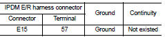
Is the check result normal? YES >> GO TO 8.
NO >> Repair or replace the malfunctioning parts.
8.DETECTION OF MALFUNCTION ITEMS
Check the following items: • Harness open circuit or short circuit between the ignition switch and IPDM E/R. Refer to PG-15, "Wiring Diagram - IGNITION POWER SUPPLY -".
• 10A fuse (No.55, IPDM E/R). Refer to PG-25, "Fuse, Connector and Terminal Arrangement".
• IPDM E/R
Is the check result normal? YES >> Check intermittent incident. Refer to GI-42, "Intermittent Incident".
NO >> Repair or replace the malfunctioning parts.
 P0715 input speed sensor A
DTC Logic
DTC DETECTION LOGIC
DTC CONFIRMATION PROCEDURE
CAUTION:
Be careful of the driving speed.
1.PREPARATION BEFORE WORK
If another "DTC CONFIRMATION PROCEDURE" occurs just befor ...
 P0740 torque converter
DTC Logic
DTC DETECTION LOGIC
DTC CONFIRMATION PROCEDURE
CAUTION:
Be careful of the driving speed.
1.PREPARATION BEFORE OPERATION (PART 1)
If another "DTC CONFIRMATION PROCEDURE" occ ...
Other materials:
Blower motor
Diagnosis Procedure
1.CHECK FUSE
1. Turn ignition switch OFF.
2. Check following fuses.
- 10A fuse [No. 15, located in fuse block (J/B)]
- 15A fuses [Nos. 14 and 16, located in fuse block (J/B)]
NOTE:
Refer to PG-22, "Fuse, Connector and Terminal Arrangement".
Is the inspection ...
System setting
Temperature Setting Trimmer
DESCRIPTION
If the temperature felt by the customer is different from the air flow
temperature controlled by the temperature
setting, the A/C auto amp. control temperature can be adjusted to compensate for
the temperature setting.
HOW TO SET
With CONSULT-III
P ...
Battery terminal with fusible link
Exploded View
1 : Battery terminal with fusible link
2 : Harness connector
: N·m (kg-m, ft-lb)
Removal and Installation
REMOVAL
1. Disconnect the battery cable from the negative terminal.
2. Remove cover of battery positive terminal.
3. Remove harness mounting nut and battery terminal with ...