Nissan Juke Service and Repair Manual : P0705 transmission range switch A
DTC Logic
DTC DETECTION LOGIC

DTC CONFIRMATION PROCEDURE
CAUTION:
Be careful of the driving speed
.
1.PREPARATION BEFORE WORK
If another "DTC CONFIRMATION PROCEDURE" occurs just before, turn ignition switch OFF and wait for at least 10 seconds, then perform the next test.
>> GO TO 2.
2.CHECK DTC DETECTION
1. Start the engine.
2. Maintain the following conditions.
Accelerator pedal position : 0.0/8
Brake pedal : Depressed
Vehicle speed : 0 km/h (0 MPH)
3. Shift the selector lever through entire positions from “P” to “L”. (Hold
the selector lever at each position for
10 seconds or more.)
4. Check the first trip DTC.
Is “P0705” detected? YES >> Go to TM-394, "Diagnosis Procedure".
NO >> INSPECTION END
Diagnosis Procedure
1.CHECK TCM INPUT SIGNALS
 With CONSULT-III
1. Turn ignition switch ON.
2. Select “Data Monitor” in “TRANSMISSION”.
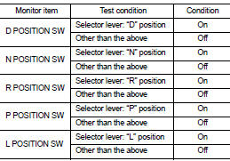
3. Select “D POSITION SW”, “N POSITION SW”, “R POSITION SW”, “P POSITION SW” and “L POSITION SW”.
4. Shift the selector lever through entire positions from “P” to “L” and check ON/OFF of each monitor item.
 Without CONSULT-III.
1. Turn the ignition switch OFF.
2. Disconnect the TCM connector.
3. Turn ignition switch ON.
4. Shift the selector lever from “P” to “L” and check the voltage between the TCM harness connector terminal and the ground.

Is the check result normal? YES >> Check intermittent incident. Refer to GI-42, "Intermittent Incident".
NO-1 [“D POSITION SW” is “ON” when selector is not in “D” position. (Or connector terminal 4 is at power voltage.)]>>GO TO 2.
NO-2 [“N POSITION SW” is “ON” when selector is not in “N” position. (Or connector terminal 5 is at power voltage.)]>>GO TO 4.
NO-3 [“R POSITION SW” is “ON” when selector is not in “R” position. (Or connector terminal 6 is at power voltage.)]>>GO TO 6.
NO-4 [“P POSITION SW” is “ON” when selector is not in “P” position. (Or connector terminal 7 is at power voltage.)]>>GO TO 8.
NO-5 [“L POSITION SW” is “ON” when selector is not in “L” position. (Or connector terminal 2 is at power voltage.)]>>GO TO 10.
2.CHECK D POSITION SW CIRCUIT (PART 1)
1. Turn the ignition switch OFF.
2. Disconnect the TCM connector.
3. Check the continuity between the TCM harness connector terminals.

Is the check result normal? YES >> GO TO 3.
NO >> Repair or replace the malfunctioning parts.
3.CHECK D POSITION SW CIRCUIT (PART 2)
1. Disconnect the transmission position switch connector.
2. Turn ignition switch ON.
3. Check the voltage between the TCM harness connector and ground.

Is the check result normal? YES >> GO TO 12.
NO >> Repair or replace the malfunctioning parts.
4.CHECK N POSITION SW CIRCUIT (PART 1)
1. Turn the ignition switch OFF.
2. Disconnect the TCM connector.
3. Check the continuity between the TCM harness connector terminals.

Is the check result normal? YES >> GO TO 5.
NO >> Repair or replace the malfunctioning parts.
5.CHECK N POSITION SW CIRCUIT (PART 2)
1. Disconnect the transmission position switch connector.
2. Turn ignition switch ON.
3. Check the voltage between the TCM harness connector and ground.

Is the check result normal? YES >> GO TO 12.
NO >> Repair or replace the malfunctioning parts.
6.CHECK P POSITION SW CIRCUIT (PART 1)
1. Turn the ignition switch OFF.
2. Disconnect the TCM connector.
3. Check the continuity between the TCM harness connector terminals.

Is the check result normal? YES >> GO TO 7.
NO >> Repair or replace the malfunctioning parts.
7.CHECK P POSITION SW CIRCUIT (PART 2)
1. Disconnect the transmission position switch connector.
2. Turn ignition switch ON.
3. Check the voltage between the TCM harness connector and ground.

Is the check result normal? YES >> GO TO 12.
NO >> Repair or replace the malfunctioning parts.
8.CHECK R POSITION SW CIRCUIT (PART1)
1. Turn the ignition switch OFF.
2. Disconnect the TCM connector.
3. Check the continuity between the TCM harness connector terminals

Is the check result normal? YES >> GO TO 9.
NO >> Repair or replace the malfunctioning parts.
9.CHECK R POSITION SW CIRCUIT (PART 2)
1. Disconnect the transmission position switch connector.
2. Turn ignition switch ON.
3. Check the voltage between the TCM harness connector and ground.

Is the check result normal? YES >> GO TO 12.
NO >> Repair or replace the malfunctioning parts.
10.CHECK 1: L POSITION SWITCH CIRCUIT (PART 1)
1. Turn the ignition switch OFF.
2. Disconnect the TCM connector.
3. Check the continuity between the TCM harness connector terminals.

Is the check result normal? YES >> GO TO 11.
NO >> Repair or replace the malfunctioning parts.
11.CHECK 2: L POSITION SWITCH CIRCUIT (PART 2)
1. Disconnect the transmission position switch connector.
2. Turn ignition switch ON.
3. Check the voltage between the TCM harness connector and ground.

Is the check result normal? YES >> GO TO 12.
NO >> Repair or replace the malfunctioning parts.
12.CHECK TRANSMISSION RANGE SWITCH
Check the transmission range switch. Refer to TM-398, "Component Inspection (Transmission Range Switch)".
Is the check result normal? YES >> Check intermittent incident. Refer to GI-42, "Intermittent Incident".
NO >> Repair or replace the malfunctioning parts.
Component Inspection (Transmission Range Switch)
1.CHECK TRANSMISSION RANGE SWITCH
Check the continuity between the transmission range switch connector terminals.


Is the inspection result normal? YES >> INSPECTION END
NO >> There is a malfunction of the transmission range switch. Replace the transaxle assembly. Refer to TM-508, "Removal and Installation".
 P062f eeprom
DTC Logic
DTC DETECTION LOGIC
DTC CONFIRMATION PROCEDURE
1.PREPARATION BEFORE WORK
If another "DTC CONFIRMATION PROCEDURE" occurs just before, turn ignition
switch OFF and wait for a ...
 P0706 transmission range sensor A
DTC Logic
DTC DETECTION LOGIC
DTC CONFIRMATION PROCEDURE
1.PREPARATION BEFORE WORK
If another "DTC CONFIRMATION PROCEDURE" occurs just before, turn ignition
switch OFF and wait for a ...
Other materials:
Seats
WARNING
• Do not ride in a moving vehicle when the seatback is reclined. This can
be dangerous. The shoulder belt will not be against your body. In an accident, you
could be thrown into it and receive neck or other serious injuries. You could also
slide under the lap belt and receive seriou ...
Back door does not opened
Diagnosis Procedure
1.CHECK BACK DOOR OPENER SWITCH
Check back door opener switch.
Refer to DLK-513, "Component Function Check".
Is the inspection result normal?
YES >> GO TO 2.
NO >> Repair or replace the malfunctioning parts.
2.CHECK BACK DOOR OPENER ACTUATOR
...
U1402 engine speed signal
DTC Logic
DTC DETECTION LOGIC
Diagnosis Procedure
1.PERFORM ECM SELF DIAGNOSIS
Using CONSULT-III, check the “self diagnosis result” of “ENGINE” and repair
or replace any malfunctioning
parts.
>> • Refer to EC-108, "DTC Index". (MR16DDT)
• Refer to EC-522, "DTC Index ...