Nissan Juke Service and Repair Manual : P0487 EGR volume control valve
DTC Logic
DTC DETECTION LOGIC

Diagnosis Procedure
1.CHECK EGR VOLUME CONTROL VALVE CONTROL CIRCUIT
1. Turn ignition switch OFF.
2. Disconnect EGR volume control valve harness connector and ECM harness connector.
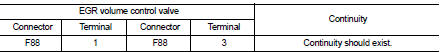
3. Check the continuity between EGR volume control valve terminal harness connector and ECM harness connector.

4. Also check harness for short to ground and short to power.
OK or NG OK >> GO TO 2.
NG >> Repair open circuit or short to ground or short to power in harness or connectors.
2.CHECK EGR VOLUME CONTROL VALVE
Refer to EC-952, "Component Inspection".
OK or NG OK >> GO TO 3.
NG >> Replace EGR volume control valve. Refer to EC-881, "Work Procedure".
3.CHECK EGR VOLUME CONTROL VALVE CONTROL POSITION SENSOR
Refer to EC-952, "Component Inspection".
OK or NG OK >> GO TO 4.
NG >> Replace EGR volume control valve. Refer to EC-881, "Work Procedure".
4.CHECK INTERMITTENT INCIDENT
Refer to GI-42, "Intermittent Incident".
>> INSPECTION END
Component Inspection
EGR VOLUME CONTROL VALVE
1. Disconnect EGR volume control valve harness connector.
2. Check resistance EGR volume control valve harness connector.

If NG, replace EGR volume control valve. Refer to EC-881, "Work Procedure".
EGR VOLUME CONTROL VALVE CONTROL POSITION SENSOR
1. Disconnect EGR volume control valve harness connector.
2. Check continuity EGR volume control valve harness connector.
If NG, replace EGR volume control valve. Refer to EC-881, "Work Procedure".
 P047B exhaust gas pressure sensor 2
DTC Logic
DTC DETECTION LOGIC
Diagnosis Proce
1.CHECK GROUND CONNECTIONS
1. Turn ignition switch OFF and wait at least 20 seconds.
2. Check ground connection E38. Refer to Ground inspection in ...
 P0488 EGR system
DTC Logic
DTC DETECTION LOGIC
Diagnosis Procedure
1.CHECK EGR VOLUME CONTROL VALVE CONTROL CIRCUIT
1. Turn ignition switch OFF.
2. Disconnect EGR volume control valve harness connector and ECM ...
Other materials:
Removal and installation
ALTERNATOR
HR16DE
HR16DE : Exploded View
REMOVAL
1. Alternator bracket mounting bolt
2. Alternator bracket
3. Alternator mounting bolt
4. Alternator
5. “B” terminal harness
6. “B” terminal nut
7. Alternator connector
: N·m (kg-m, ft-lb)
DISASSEMBLY
Type: A002TJ1291ZE
1. Rear be ...
Symptom diagnosis
COMBINATION SWITCH SYSTEM SYMPTOMS
Symptom Table
1. Perform “Data Monitor” of CONSULT-III to check for any malfunctioning
item.
2. Check the malfunction combinations.
3. Identify the malfunctioning part from the agreed combination and repair or
replace the part.
...
4WD mode indicator lamp (4WD)
Component Function Check
1.4WD MODE INDICATOR LAMP OPERATION CHECK
Check that 4WD mode indicator lamp (4WD) turns on for approximately 1 second
after the ignition switch is
turned ON.
Is the inspection result normal?
YES >> INSPECTION END
NO >> Proceed to diagnosis procedure. R ...