Nissan Juke Service and Repair Manual : P0217 engine over temperature
DTC Logic
DTC DETECTION LOGIC
If the cooling fan or another component in the cooling system malfunctions, engine coolant temperature will rise.
When the engine coolant temperature reaches an abnormally high temperature condition, a malfunction is indicated.

Diagnosis Procedure
1.CHECK COOLING FAN LOW SPEED FUNCTION
1. Start engine and let it idle.
2. Turn air conditioner switch and blower fan switch ON.
3. Make sure that cooling fan operates at low speed.
Is the inspection result normal? YES >> GO TO 2.
NO >> Refer to EC-1015, "Diagnosis Procedure".
2.CHECK COOLING FAN HIGH SPEED FUNCTION
1. Turn ignition switch OFF.
2. Turn air conditioner switch and blower fan switch OFF.
3. Disconnect engine coolant temperature sensor harness connector.
4. Connect 150 Ω resistor to engine coolant temperature sensor harness connector.
5. Restart engine and make sure that cooling fan operates at higher speed than low speed.
Is the inspection result normal? YES >> GO TO 3.
NO >> Refer to EC-1015, "Diagnosis Procedure".
3.CHECK COOLING SYSTEM FOR LEAK-I
Check cooling system for leak. Refer to CO-62, "Inspection".
Is leakage detected? YES >> GO TO 4.
NO >> GO TO 5.
4.CHECK COOLING SYSTEM FOR LEAK-II
Check the following for leak. Refer to CO-62, "Inspection".
• Hose
• Radiator
• Water pump
>> Repair or replace malfunctioning part.
5.CHECK RESERVOIR TANK CAP
Check reservoir tank cap. Refer to CO-65, "Inspection".
Is the inspection result normal? YES >> GO TO 6.
NO >> Replace reservoir tank cap.
6.CHECK THERMOSTAT
Check thermostat. Refer to CO-74, "Inspection".
Is the inspection result normal? YES >> GO TO 7.
NO >> Replace thermostat.
7.CHECK ENGINE COOLANT TEMPERATURE SENSOR
Refer to EC-908, "Component Inspection".
Is the inspection result normal? YES >> GO TO 8.
NO >> Replace engine coolant temperature sensor.
8.CHECK MAIN 12 CAUSES
If the cause cannot be isolated, check the following.
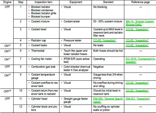
*1: Engine running at idle speed.
*2: Engine running at 3,000 rpm for 10 minutes.
*3: Drive at 90 km/h (55 MPH) for 30 minutes and then let idle for 10 minutes.
*4: After 60 minutes of cool down time.
For more information, refer to CO-60, "Troubleshooting Chart".
>> INSPECTION END
 P0201, P0202, P0203, P0204 fuel injector
DTC Logic
DTC DETECTION LOGIC
NOTE:
If DTC P0201, P0202, P0203 or P0204 is displayed with DTC P0263, P0266, P0269 or
P0272 first perform
trouble diagnosis for DTC P0263, P0266, P0269 or P0272. ...
 P0225 APP sensor
DTC Logic
DTC DETECTION LOGIC
NOTE:
• If DTC P0225 is displayed with DTC P0641, first perform trouble diagnosis for
DTC P0641. Refer to
EC-974, "DTC Logic".
Diagnosis Procedure
1.C ...
Other materials:
P1586 G sensor
DTC Logic
DTC DETECTION LOGIC
DTC CONFIRMATION PROCEDURE
CAUTION:
Be careful of the driving speed.
1.PREPARATION BEFORE WORK
If another "DTC CONFIRMATION PROCEDURE" occurs just before, turn ignition
switch OFF and wait for at
least 10 seconds, then perform the next test.
> ...
P0697 sensor power supply
DTC Logic
DTC DETECTION LOGIC
Diagnosis Procedure
1.CHECK GROUND CONNECTION
1. Turn ignition switch OFF and wait at least 4 minutes.
2. Check ground connection E38. Refer to Ground Inspection in GI-44, "Circuit
Inspection".
Is the inspection result normal?
YES >> GO TO 2 ...
Rear door lock
Exploded View
1. Outside handle assembly
2. Inside handle
3. TORX bolt
4. Door lock assembly
5. Rear door sealing screen
: Clip
: Pawl
: Vehicle front
: Do not reuse
: N·m (kg-m, in-lb)
: Body grease
Door lock
DOOR LOCK : Removal and Installation
REMOVAL
1. Remove rear door glass ...