Nissan Juke Service and Repair Manual : P012A TC boost sensor
DTC Logic
DTC DETECTION LOGIC

Diagnosis Procedure
1.CHECK GROUND CONNECTIONS
1. Turn ignition switch OFF.
2. Check ground connection E38. Refer to Ground inspection in GI-44, "Circuit Inspection".
Is the inspection result normal? YES >> GO TO 2.
NO >> Repair or replace ground connection.
2.CHECK TUBOCHARGER BOOST SENSOR SUPPLY CIRCUIT
1. Disconnect turbocharger boost sensor harness connector.
2. Turn ignition switch ON.
3. Check the voltage between turbocharger boost sensor connector and ground.

Is the inspection result normal? YES >> GO TO 3.
NO >> Repair open circuit or short to ground or short to power in harness or connectors.
3.CHECK TUBOCHARGER BOOST SENSOR GROUND CIRCUIT FOR OPEN AND SHORT
1. Turn ignition switch OFF.
2. Disconnect ECM harness connector.
3. Check the continuity between turbocharger boost sensor harness connector and ECM harness connector

4. Also check harness for short to ground and short to power.
Is the inspection result normal? YES >> GO TO 4.
NO >> Repair open circuit or short to ground or short to power in harness or connectors.
4.CHECK TUBOCHARGER BOOST SENSOR INPUT SIGNAL CIRCUIT FOR OPEN AND SHORT
1. Check the continuity between turbocharger boost sensor harness connector and ECM harness connector.

2. Also check harness for short to ground and short to power.
Is the inspection result normal?
YES >> GO TO 5.
NO >> Repair open circuit or short to ground or short to power in harness or connectors.
5.CHECK TUBOCHARGER BOOST SENSOR
Refer to EC-912, "Component Inspection".
Is the inspection result normal? YES >> GO TO 6.
NO >> Replace turbocharger boost sensor.
6.REPLACE ECM
1. Perform EC-879, "Work Procedure".
2. Perform EGR volume control valve closed position learning. Refer to EC-881, "Work Procedure".
>> INSPECTION END
Component Inspection
1.CHECK TURBOCHARGER BOOST SENSOR-I
1. Turn ignition switch OFF.
2. Remove turbocharger boost sensor with its harness connected.
3. Turn ignition switch ON.
4. Select ???DATA MONITOR??? mode with CONSULT-III.
5. Check ???BOOST PRESS??? and ???ATOMOS PRESS??? indication.
If the value is not very close to ???ATOMOS PRESS???, maximum pressure difference between ???ATOMOS PRESS??? and ???BOOST PRESS??? with the ignition switch ON (engine stop) = ?± 50 mbar? YES >> GO TO 2.
NO >> Replace turbocharger boost sensor.
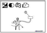
2.CHECK TURBOCHARGER BOOST SENSOR-II
1. Use pump (A) to apply turbocharger boost sensor (1) as shown in the figure.
2. Apply a pressure of between 10 kPa (0.100 bar, 0.102 kg/cm2, 1.5 psi) - 13 kPa (0.130 bar, 0.133 kg/cm2, 1.9 psi) [maximum pressure to be applied: 13 kPa (0.130 bar, 0.133 kg/cm2, 1.9 psi)].
3. Select ???DATA MONITOR??? mode with CONSULT-III.
4. Check ???BOOST PRESS??? indication with that given by the vacuum pump.
If there is no discrepancy? YES >> INSPECTION END
NO >> Replace turbocharger boost sensor.
 P0120 TP sensor
DTC Logic
DTC DETECTION LOGIC
Diagnosis Procedure
1.CHECK GROUND CONNECTIONS
1. Turn ignition switch OFF and wait at least 20 seconds.
2. Check ground connection E38. Refer to Ground inspection ...
 P012B TC boost sensor
DTC Logic
DTC DETECTION LOGIC
Diagnosis Procedure
1.CHECK GROUND CONNECTIONS
1. Turn ignition switch OFF.
2. Check ground connection E38. Refer to Ground inspection in GI-44, "Circuit
In ...
Other materials:
Rear suspension assembly
Exploded View
1. Rear suspension member
2. Rebound stopper
3. Washer
: Vehicle front
N·m (kg-m, ft-lb)
Removal and Installation
REMOVAL
1. Remove tires. Refer to WT-7, "Removal and Installation".
2. Remove center pipe. Refer to EX-6, "Removal and Installation".
3. ...
Front wiper does not operate
Description
The front wiper does not operate under any operation conditions.
Diagnosis Procedure
1.CHECK WIPER RELAY OPERATION
CONSULT-III ACTIVE TEST
1. Select “FRONT WIPER” of IPDM E/R active test item.
2. With operating the test item, check front wiper operation.
Lo : Front wiper LO operat ...
Fuel filler lid opener
Exploded View
1. Fuel filler lid opener cable
2. Cable protector
3. Fuel filler lid lock assembly
4. Fuel filler lid assembly
5. Spring
6. Bumper rubber
: Clip
: Do not reuse
Fuel filler lid
FUEL FILLER LID : Removal and Installation
REMOVAL
1. Fully open fuel filler lid.
2. Remove ...