Nissan Juke Service and Repair Manual : Oil pan
Exploded View

1. Baffle plate
2. Gasket
3. Oil pan
4. O-ring
5. Drain plug
6. Oil level gauge guide
7. Transaxle
8. Crankshaft position sensor (POS)
 : N·m (kg-m, ft-lb)
 : N·m (kg-m, in-lb)
 : Always replace after every
disassembly.
Removal and Installation
REMOVAL
CAUTION:
Never drain engine oil when the engine is hot to avoid the danger of being
scalded.
1. Remove engine under cover.
2. Remove RH front wheel. Refer to WT-7, "Exploded View".
3. Remove fender protector RH. Refer to EXT-22, "Exploded View".
4. Remove engine mounting bracket. Refer to EM-326, "Exploded View".
5. Remove center bearing bracket as shown.

6. Remove A/C compressor bracket mounting bolt as shown.

7. Remove oil level gauge guide.
8. Drain engine oil. Refer to LU-34, "Draining".
CAUTION:
Perform when engine is cold.
9. Remove oil pan and transaxle joint bolts.
10. Support the engine bottom of the oil pan with a transmission jack etc.

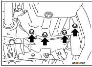
11. Remove oil pan bolt reverse order as shown.

• Insert seal cutter (special service tool) between upper oil pan and cylinder block. Slide tool by tapping on the side of the tool with a hammer.
CAUTION:
Exercise care not to damage mating surface.

12. Remove oil pan and baffle plate.
INSTALLATION
• Install in the reverse order of removal paying attention to the following.
1. Apply liquid gasket as shown.
• Use Genuine Liquid Gasket or equivalent.

2. Install baffle plate.
3. Install oil pan.
• Tighten the mounting bolts of oil pan on the clutch housing without locking.
• Tighten the bolts in the numerical order shown in the figure.
 : 14 N·m (1.4 kg-m, 10 ft-lb)

• Tighten the mounting bolts of oil pan on the clutch housing.
 : 44 N·m (4.5 kg-m, 10 ft-lb)
4. At least 30 minutes after oil pan is installed, pour engine oil.

Inspection
INSPECTION AFTER REMOVAL
Clean oil pump assembly if any object attached.
INSPECTION AFTER INSTALLATION
• Inspection the engine oil level. Refer to LU-33, "Inspection".
• Start the engine, and make sure there is no leak of engine oil. Refer to LU-33, "Inspection".
 Exhaust manifold
Exploded View
1. Exhaust gas temperature sensor 1
2. Gasket
3. Exhaust manifold
4. Exhaust gas pressure sensor 1
A. To cylinder head
: N·m (kg-m, ft-lb)
: Always replace after every
disas ...
 Glow plug
Exploded View
1. Glow plug
Engine front
: N·m (kg-m, ft-lb)
Removal and Installation
REMOVAL
CAUTION:
Remove glow plug only if necessary. If carbon adheres, it may be stuck and
broken.
1. ...
Other materials:
Jump starting
To start your engine with a booster battery, the instructions and precautions
below must be followed.
WARNING
• If done incorrectly, jump starting can lead to a battery explosion, resulting
in severe injury or death.
It could also damage your vehicle.
• Explosive hydrogen gas is always prese ...
Radiator core support
HR16DE
HR16DE : Exploded View
1. Radiator core support upper
2. Air guide RH (MT models)
3. Radiator core support lower
4. Air guide LH
5. Air guide (upper)
6. Air guide LH (CVT models)
7. Air guide RH (CVT models)
: N·m (kg-m, ft-lb)
HR16DE : Removal and Installation
RADIATOR CORE ...
B2268 water temp
Description
The engine coolant temperature signal is transmitted from ECM to the
combination meter via CAN communication.
DTC Logic
DTC DETECTION LOGIC
Diagnosis Procedure
1.PERFORM SELF-DIAGNOSIS OF ECM
Perform “Self Diagnosis Result” of “ENGINE”, and repair or replace
malfunctioning pa ...