Nissan Juke Service and Repair Manual : Key switch
Component Function Check
1.CHECK FUNCTION
1. Select “DOOR LOCK” of “BCM” using CONSULT-III.
2. Select “KEY ON SW” in “DATA MONITOR” mode.
3. Check that the function operates normally according to the following conditions.

Is the inspection result normal? YES >> Key switch is OK.
NO >> Refer to DLK-401, "Diagnosis Procedure".
Diagnosis Procedure
1.CHECK FUSE
1. Turn ignition switch OFF.
2. Check 10 A fuse, [No.7, located in fuse block (J/B)].
Is fuse fusing? YES >> Replace the blown fuse after repairing the affected circuit if a fuse is blown.
NO >> GO TO 2.
2.CHECK KEY SWITCH POWER SUPPLY CIRCUIT

Is the inspection result normal? YES >> GO TO 3.
NO >> Repair or replace harness.
3.CHECK KEY SWITCH CIRCUIT
1. Disconnect BCM connector.
2. Check continuity between key switch harness connector and BCM harness connector.

3. Check continuity between key switch connector and ground.
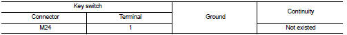
Is the inspection result normal? YES >> GO TO 4 NO >> Repair or replace harness.
4.CHECK KEY SWITCH
Refer to DLK-402, "Component Inspection".
Is the inspection result normal? YES >> GO TO 5.
NO >> Replace key switch.
5.CHECK INTERMITTENT INCIDENT
Refer to GI-42, "Intermittent Incident".
>> INSPECTION END
Component Inspection
COMPONENT INSPECTION
1.CHECK KEY SWITCH
1. Turn ignition switch OFF.
2. Disconnect key switch connector.
3. Check continuity between key switch terminals.

Is the inspection result normal? YES >> INSPECTION END
NO >> Replace key switch.
 Hazard function
Component Function Check
1.CHECK FUNCTION
1. Select “MULTI REMOTE ENT” of “BCM” using CONSULT-III.
2. Select “FLASHER” in “ACTIVE TEST” mode.
3. Check that the function operates normally according ...
 Keyfob battery
Component Function Check
1.CHECK FUNCTION
Check door lock and unlock operation with keyfob button.
Is the inspection result normal?
YES >> Keyfob is OK.
NO >> Refer to DLK-403, &q ...
Other materials:
Diagnosis Procedure
WARNING:
• Before servicing, turn ignition switch OFF, disconnect battery negative
terminal and wait at least 3
minutes. (To discharge backup capacitor.)
• Never use unspecified tester or other measuring device.
1.CHECK HARNESS CONNECTOR
Check the harness connector.
Is the inspection res ...
P0234 TC system
DTC Logic
DTC DETECTION LOGIC
NOTE:
If DTC P0234 is displayed with DTC P0237 or P0238, first perform the trouble
diagnosis for DTC P0237 or
P0238. Refer to EC-260, "DTC Logic".
DTC CONFIRMATION PROCEDURE
1.PERFORM COMPONENT FUNCTION CHECK
Perform component function check. Refer ...
Blower motor
Exploded View
2WD models
1. A/C unit assembly
2. Fan control amp.*1
3. Blower fan resistor*2
4. Blower motor
5. Blower motor cover
• *1: Automatic air conditioner
• *2: Manual air conditioner or Manual heater
4WD models
1. A/C unit assembly
2. Blower fan resistor*1
3. Sub harnes ...