Nissan Juke Service and Repair Manual : Front wiper auto stop signal circuit
Component Function Check
1.CHECK FRONT WIPER (AUTO STOP) SIGNAL
 CONSULT-III DATA MONITOR
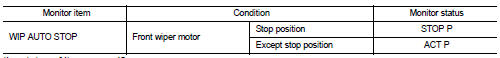
1. Select “WIP AUTO STOP” of IPDM E/R data monitor item.
2. Operate the front wiper.
3. With the front wiper operation, check the monitor status.
Is the status of item normal? YES >> Auto stop signal circuit is normal.
NO >> Refer to WW-40, "Diagnosis Procedure".
Diagnosis Procedure
1.CHECK IPDM E/R OUTPUT VOLTAGE
1. Turn ignition switch OFF.
2. Disconnect front wiper motor connector.
3. Turn ignition switch ON.
4. Check voltage between front wiper motor harness connector and ground.

Is the inspection result normal? YES >> Replace front wiper motor.
NO >> GO TO 2.
2.CHECK FRONT WIPER MOTOR (AUTO STOP) CIRCUIT
1. Turn ignition switch OFF.
2. Disconnect IPDM E/R connector.
3. Check continuity between IPDM E/R harness connector and front wiper motor harness connector.

4. Check continuity between IPDM E/R harness connector and ground.

Is the inspection result normal? YES >> Replace IPDM E/R.
NO >> Repair or replace harness.
 Front wiper motor hi circuit
Component Function Check
1.CHECK FRONT WIPER HI OPERATION
CONSULT-III ACTIVE TEST
1. Select “FRONT WIPER” of IPDM E/R active test item.
2. With operating the test item, check front wiper operation ...
 Front wiper motor ground circuit
Diagnosis Procedure
1.CHECK FRONT WIPER MOTOR GROUND CIRCUIT
1. Turn ignition switch OFF.
2. Disconnect front wiper motor connector.
3. Check continuity between front wiper motor harness connector ...
Other materials:
Wiring diagram
AUDIO WITHOUT NAVIGATION
Wiring Diagram
For connector terminal arrangements, harness layouts, and alphabets in a
(option abbreviation; if not
described in wiring diagram), refer to GI-12, "Connector Information/Explanation
of Option Abbreviation".
...
Service Notice or Precautions for Transfer
• After overhaul refill the transfer with new transfer oil.
• Check the oil level or replace the oil only with the vehicle parked on level
surface.
• During removal or installation, keep inside of transfer clear of dust or
dirt.
• Replace all tires at the same time. Always use tires of the pr ...
U1000 can comm circuit
Description
CAN (Controller Area Network) is a serial communication line for real time
applications. It is an on-vehicle multiplex
communication line with high data communication speed and excellent error
detection ability. Modern
vehicle is equipped with many electronic control unit, and eac ...