Nissan Juke Service and Repair Manual : Door switch
Component Function Check
1.CHECK FUNCTION
1. Select “DOOR LOCK” of “BCM” using CONSULT-III.
2. Select “DOOR SW-DR”, “DOOR SW-AS”, “DOOR SW-RL”, “DOOR SW-RR”, “BACK DOOR SW” in “DATA MONITOR” mode.
3. Check that the function operates normally according to the following conditions.

Is the inspection result normal? YES >> Door switch is OK.
NO >> Refer to DLK-397, "Diagnosis Procedure".
Diagnosis Procedure
1.CHECK DOOR SWITCH INPUT SIGNAL
1. Turn ignition switch OFF.
2. Disconnect malfunctioning door switch connector.
3. Check signal between malfunctioning door switch harness connector and ground using oscilloscope.

Is the inspection result normal? YES-1 >> Back door: GO TO 3.
YES-2 >> other door: GO TO 4.
NO >> GO TO 2.
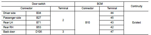
2.CHECK DOOR SWITCH CIRCUIT
1. Disconnect BCM connector.
2. Check continuity between door switch harness connector and BCM harness connector.
3. Check continuity between door switch harness connector and ground.

Is the inspection result normal? YES >> Replace BCM. Refer to BCS-161, "Removal and Installation".
NO >> Repair or replace harness.
3.CHECK BACK DOOR SWITCH CIRCUIT
Check continuity between back door lock assembly harness connector and ground.

Is the inspection result normal? YES >> GO TO 4.
NO >> Repair or replace harness.
4.CHECK DOOR SWITCH
Refer to DLK-398, "Component Inspection".
Is the inspection result normal? YES >> GO TO 5.
NO >> Replace malfunctioning door switch.
5.CHECK INTERMITTENT INCIDENT
Refer to GI-42, "Intermittent Incident".
>> INSPECTION END
Component Inspection
1.CHECK DOOR SWITCH
1. Turn ignition switch OFF.
2. Disconnect malfunctioning door switch connector.
3. Check continuity between door switch terminals.

Is the inspection result normal? YES >> INSPECTION END
NO >> Replace malfunction door switch.
 Door lock status indicator
Component Function Check
1.CHECK FUNCTION
1. Select “DOOR LOCK” of “BCM” using CONSULT-III.
2. Select “DOOR LOCK IND” in “ACTIVE TEST” mode.
3. Check that the function operates normally according ...
 Hazard function
Component Function Check
1.CHECK FUNCTION
1. Select “MULTI REMOTE ENT” of “BCM” using CONSULT-III.
2. Select “FLASHER” in “ACTIVE TEST” mode.
3. Check that the function operates normally according ...
Other materials:
Engine unit
Disassembly
1. Remove intake manifold. Refer to EM-163, "Exploded View".
2. Remove exhaust manifold. Refer to EM-166, "Exploded View".
3. Remove oil pan (lower). Refer to EM-169, "Exploded View".
4. Remove ignition coil, spark plug, and rocker cover. Refer to EM-17 ...
Remote keyless entry system (if so equipped)
It is possible to lock/unlock all doors (including the lift gate), and activate
the panic alarm by using the keyfob from outside the vehicle.
Before locking the doors, make sure the key is not left in the vehicle.
The keyfob can operate at a distance of approximately 33 ft (10 m) from the vehic ...
Additional service when replacing TCM
Description
Always perform the following items when the TCM is replaced.
CHECK LOADING OF CALIBRATION DATA
• The TCM acquires calibration data (individual characteristic value) of each
solenoid that is stored in the
ROM assembly (in the control valve). This enables the TCM to perform accurate ...