Nissan Juke Service and Repair Manual : Door lock actuator
Driver side
DRIVER SIDE : Component Function Check
1.CHECK FUNCTION
1. Select “DOOR LOCK” of “BCM” using CONSULT-III.
2. Select “DOOR LOCK” in “ACTIVE TEST” mode.
3. Check that the function operates normally according to the following conditions.

Is the inspection result normal? YES >> Door lock actuator is OK.
NO >> Refer to DLK-386, "DRIVER SIDE : Diagnosis Procedure".
DRIVER SIDE : Diagnosis Procedure
1.CHECK DOOR LOCK ACTUATOR INPUT SIGNAL
1. Turn ignition switch OFF.
2. Disconnect front door lock assembly (driver side) connector.
3. Check voltage between front door lock assembly (driver side) harness connector and ground.

Is the inspection result normal? YES >> Replace front door lock assembly (driver side).
NO >> GO TO 2.
2.CHECK DOOR LOCK ACTUATOR CIRCUIT
1. Disconnect BCM connector and all door lock assembly connector.
2. Check continuity between BCM harness connector and front door lock assembly (driver side) harness connector

3. Check continuity between BCM harness connector and ground.

Is the inspection result normal? YES >> GO TO 3.
NO >> Repair or replace harness.
3.CHECK BCM OUTPUT SIGNAL
1. Connect BCM connector.
2. Check voltage between BCM harness connector and ground.

Is the inspection result normal? YES >> Check for internal short of each door lock actuator.
NO >> Replace BCM. Refer to BCS-161, "Removal and Installation".
Passenger side
PASSENGER SIDE : Component Function Check
1.CHECK FUNCTION
1. Select “DOOR LOCK” of “BCM” using CONSULT-III.
2. Select “DOOR LOCK” in “ACTIVE TEST” mode.
3. Check that the function operates normally according to the following conditions.

Is the inspection result normal? YES >> Door lock actuator is OK.
NO >> Refer to DLK-386, "DRIVER SIDE : Diagnosis Procedure".
PASSENGER SIDE : Diagnosis Procedure
1.CHECK DOOR LOCK ACTUATOR INPUT SIGNAL
1. Turn ignition switch OFF.
2. Disconnect front door lock assembly (passenger side) connector.
3. Check voltage between front door lock assembly (passenger side) harness connector and ground.

Is the inspection result normal? YES >> Replace front door lock assembly (passenger side).
NO >> GO TO 2.
2.CHECK DOOR LOCK ACTUATOR CIRCUIT
1. Disconnect BCM connector and all door lock assembly connector.
2. Check continuity between BCM harness connector and front door lock assembly (passenger side) harness connector.

3. Check continuity between BCM harness connector and ground.

Is the inspection result normal? YES >> GO TO 3.
NO >> Repair or replace harness.
3.CHECK BCM OUTPUT SIGNAL
1. Connect BCM connector.
2. Check voltage between BCM harness connector and ground.

Is the inspection result normal? YES >> Check for internal short of each door lock actuator.
NO >> Replace BCM. Refer to BCS-161, "Removal and Installation".
Rear LH
REAR LH : Component Function Check
1.CHECK FUNCTION
1. Select “DOOR LOCK” of “BCM” using CONSULT-III.
2. Select “DOOR LOCK” in “ACTIVE TEST” mode.
3. Check that the function operates normally according to the following conditions.

Is the inspection result normal? YES >> Door lock actuator is OK.
NO >> Refer to DLK-386, "DRIVER SIDE : Diagnosis Procedure".
REAR LH : Diagnosis Procedure
1.CHECK DOOR LOCK ACTUATOR INPUT SIGNAL
1. Turn ignition switch OFF.
2. Disconnect rear door lock assembly LH connector.
3. Check voltage between rear door lock assembly LH harness connector and ground.

Is the inspection result normal? YES >> Replace rear door lock assembly LH.
NO >> GO TO 2.
2.CHECK DOOR LOCK ACTUATOR CIRCUIT
1. Disconnect BCM connector and all door lock assembly connector.
2. Check continuity between BCM harness connector and rear door lock assembly LH harness connecto

3. Check continuity between BCM harness connector and ground.

Is the inspection result normal? YES >> GO TO 3.
NO >> Repair or replace harness.
3.CHECK BCM OUTPUT SIGNAL
1. Connect BCM connector.
2. Check voltage between BCM harness connector and ground.

Is the inspection result normal? YES >> Check for internal short of each door lock actuator.
NO >> Replace BCM. Refer to BCS-161, "Removal and Installation".
Rear RH
REAR RH : Component Function Check
1.CHECK FUNCTION
1. Select “DOOR LOCK” of “BCM” using CONSULT-III.
2. Select “DOOR LOCK” in “ACTIVE TEST” mode.
3. Check that the function operates normally according to the following conditions.

Is the inspection result normal? YES >> Door lock actuator is OK.
NO >> Refer to DLK-386, "DRIVER SIDE : Diagnosis Procedure".
REAR RH : Diagnosis Procedure
1.CHECK DOOR LOCK ACTUATOR INPUT SIGNAL
1. Turn ignition switch OFF.
2. Disconnect rear door lock assembly RH connector.
3. Check voltage between rear door lock assembly RH harness connector and ground.
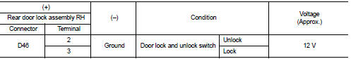
Is the inspection result normal? YES >> Replace rear door lock assembly RH.
NO >> GO TO 2.
2.CHECK DOOR LOCK ACTUATOR CIRCUIT
1. Disconnect BCM connector and all door lock assembly connector.
2. Check continuity between BCM harness connector and rear door lock assembly RH harness connector.

3. Check continuity between BCM harness connector and ground.

Is the inspection result normal? YES >> GO TO 3.
NO >> Repair or replace harness.
3.CHECK BCM OUTPUT SIGNAL
1. Connect BCM connector.
2. Check voltage between BCM harness connector and ground.

Is the inspection result normal? YES >> Check for internal short of each door lock actuator.
NO >> Replace BCM. Refer to BCS-161, "Removal and Installation".
 Back door opener switch
Component Function Check
1.CHECK FUNCTION
1. Select “TRUNK” of “BCM” using CONSULT-III.
2. Select “TRNK OPNR SW” in “DATA MONITOR” mode.
3. Check that the function operates normally according to t ...
 Door lock and unlock switch
Driver side
DRIVER SIDE : Component Function Check
1.CHECK FUNCTION
1. Select “DOOR LOCK” of “BCM” using CONSULT-III.
2. Select “CDL LOCK SW”, “CDL UNLOCK SW” in “DATA MONITOR” mode.
3. Check tha ...
Other materials:
Ignition signal
Component Function Check
1.INSPECTION START
Turn ignition switch OFF, and restart engine.
Does the engine start?
YES >> GO TO 2.
NO >> Proceed to EC-414, "Diagnosis Procedure".
2.IGNITION SIGNAL FUNCTION
With CONSULT-III
1. Perform “POWER BALANCE” in “ACTIVE TEST” ...
Front wiper arm
Exploded View
RHD models
1. Front wiper arm cap
2. Front wiper arm RH
3. Front wiper drive assembly
4. Front wiper motor
5. Front wiper blade LH
6. Front wiper arm LH
7. Front wiper blade RH
: Pawl
: N·m (kg-m, in-lb)
: N·m (kg-m, ft-lb)
LHD models
1. Front wiper arm cap
2. Fr ...
Keyfob ID registration
Description
Perform the following procedure after BCM is replaced or when new keyfob ID
is registered
NOTE:
When registering the keyfob ID, perform only one procedure to simultaneously
register both ID (IMMOBILIZER
ID and keyfob ID).
Work Procedure
1.STEP 1
Close all doors.
>> GO ...