Nissan Juke Service and Repair Manual : Differential side oil seal
Exploded View
 1. Transaxle assembly
2. Differential side oil seal (left side)
3. Differential side oil seal (right side)
 : Vehicle front
 : Always replace after every
disassembly.
 : Genuine NISSAN CVT Fluid NS-2
Removal and Installation
REMOVAL
NOTE
:
Cap or plug openings to prevent fluid from spilling.
1. Remove the left and right front drive shafts. Refer to FAX-53, "Removal and Installation".
2. Use oil seal remover or a similar means and remove the differential side oil seal.
CAUTION:
When removing the differential side oil seal, be careful not to scratch the oil
seal mounting surfaces
of the transaxle case and converter housing.
INSTALLATION
Note the following, and install in the reverse order of removal.
CAUTION:
• Never reuse differential side oil seal.
• Apply Genuine NISSAN CVT Fluid NS-2 to the differential side oil seal lip and around the oil seal.
• When inserting the drive shaft, be sure to use a protector (SST: KV38107900). Refer to FAX-53, "Removal and Installation".
Use a drift (commercial service tool) and drive the differential side oil seal in until the amount of oil seal projection from the case edge matches dimensions (C) and (D).
CAUTION:
Be careful not to scratch the lip of the differential side oil seal
when press-fitting it.
A : Differential side oil seal (left side) B : Differential side oil seal (right side)
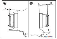
Dimension “C” :Height difference from case end surface is within 1.8 ± 0.5 mm (0.071 ± 0.020 in).
Dimension “D” :Height difference from case end surface is within 1.8 ± 0.5 mm (0.071 ± 0.020 in).
NOTE
:
The reference is the pull-in direction of the differential side oil seal.

Inspection and Adjustment
INSPECTION AFTER INSTALLATION
Check for CVT fluid leakage. Refer to TM-480, "Inspection".
ADJUSTMENT AFTER INSTALLATION
Adjust the CVT fluid level. Refer to TM-379, "Adjustment".
 Output speed sensor
Exploded View
1. Transaxle assembly
2. Output speed sensor
3. O-ring
: Vehicle front
: Always replace after every
disassembly.
: N·m (kg-m, in-lb)
: Genuine NISSAN CVT Fluid NS-2
Removal ...
 Water hose
Exploded View
1. Hose clamp
2. Water hose A
3. Water hose B
4. Water hose B
5. Water bypass pipe
6. Hose clamp
7. Heater hose
8. Water hose C
A. Water outlet
B. Heater thermostat
C ...
Other materials:
Reservoir tank cap
Inspection
• Check valve seat of reservoir tank cap.
- Check if valve seat (A) is swollen to the extent that the edge of the
metal plunger (B) cannot be seen when watching it vertically from
the top.
- Check if valve seat has no soil and damage.
• Pull negative-pressure valve to open it, a ...
Electric power steering system
WARNING
• If the engine is not running or is turned off while driving, the power assist
for the steering will not work.
Steering will be harder to operate.
• When the electric power steering warning light illuminates with the engine
running, the power assist for the steering will cease ...
Precaution Necessary for Steering Wheel Rotation
after Battery Disconnect
NOTE:
• Before removing and installing any control units, first turn the push-button
ignition switch to the LOCK position,
then disconnect both battery cables.
• After finishing work, confirm that all control unit connectors are connected
properly, then re-connect both
battery cables.
• Alw ...