Nissan Juke Service and Repair Manual : Diagnosis system (combination meter)
On Board Diagnosis Function
ON BOARD DIAGNOSIS ITEM
The combination meter allows the following diagnosis items with the on-board diagnosis function.

METHOD OF STARTING
1. Turn ignition switch ON, and switch the trip meter to “trip A” or “trip B”.
2. Turn ignition switch OFF.
3. While pressing the meter control switch (1), turn ignition switch ON.
4. Make sure that the trip meter displays “0000.0”.
5. Press the meter control switch at least 3 times. (Within 7 seconds after the ignition switch is turned ON.)

6. The combination meter is turned to self-diagnosis mode.
All of the segments of engine coolant temperature gauge, fuel gauge, odo/trip meter, shift position indicator (A) for CVT models and information display illuminate.
NOTE
:
• Check combination meter power supply and ground circuit
when the self-diagnosis mode of the combination meter does
not start. Replace combination meter if power supply and
ground circuit are normal.
• If any of the dots are not displayed, replace combination meter.
• For M/T models, start-up lamp (B) illuminate instead of shift position indicator.
7. Each meter activates by pressing the meter control switch.


NOTE
:
• If any of the meters or gauges is not activated, replace combination meter.
• The figure is reference.
Consult-III Function
CONSULT-III APPLICATION ITEMS
CONSULT-III can perform the following diagnosis modes via CAN communication and the combination meter.

SELF DIAG RESULT
Refer to MWI-36, "DTC Index".
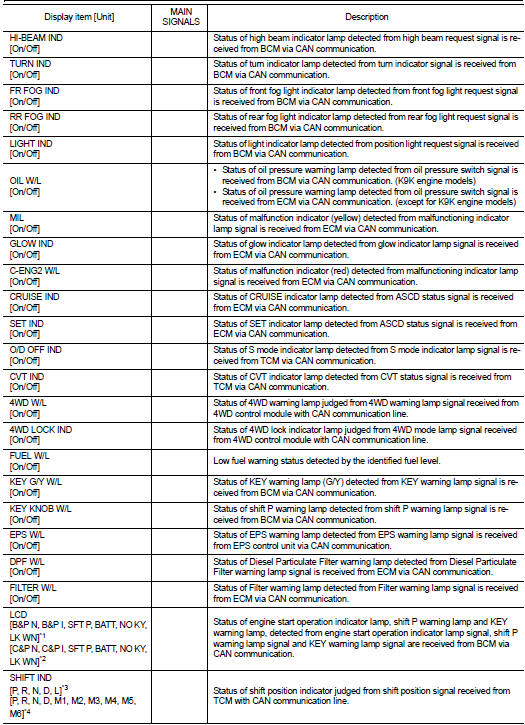
DATA MONITOR
Display Item List


• *1: CVT models
• *2: M/T models
• *3: Without manual mode CVT
• *4: With manual mode CVT
NOTE
:
Some items are not available according to vehicle specification.
SPECIAL FUNCTION
Special menu

W/L ON HISTORY
• Stores histories when warning/indicator lamp is turned on.
• “W/L ON HISTORY” indicates the “TIME” when the warning/ indicator lamp is turned on.
• The “TIME” above is:
- 0: The condition that the warning/indicator lamp has been turned on 1 or more
times after starting the engine
and waiting for 30 seconds.
- 1 - 39: The number of times the engine was restarted after the 0 condition.
- NO W/L ON HISTORY: Stores NO (0) turning on history of warning/indicator lamp.
NOTE
:
• W/L ON HISTORY is not stored for approximately 30 seconds after the engine
starts.
• Brake warning lamp does not store any history when the parking brake is applied or the brake fluid level gets low.
Display Item


 Operation
Switch Name and Function
...

Other materials:
Outside key antenna
Driver side
DRIVER SIDE : Removal and Installation
REMOVAL
Remove the driver side outside handle. Refer to DLK-176, "OUTSIDE HANDLE :
Removal and Installation".
INSTALLATION
Install in the reverse order of removal.
Passenger side
PASSENGER SIDE : Removal and Installation
REMOVA ...
Precautions on child restraints
WARNING
• Failure to follow the warnings and instructions for proper use and installation
of child restraints could result in serious injury or death of a child or other
passengers in a sudden stop or collision:
— The child restraint must be used and installed properly. Always follow all of
...
Audio unit
Removal and Installation
REMOVAL
1. Remove cluster lid C. Refer to IP-12, "Exploded View".
2. Remove audio unit screws.
3. Disconnect audio unit connectors to remove audio unit and brackets as a
single unit.
4. Remove brackets screws to remove audio unit.
INSTALLATION
1. Install ...