Nissan Juke Service and Repair Manual : Diagnosis system (audio unit)
Models with usb connection function
MODELS WITH USB CONNECTION FUNCTION : On Board Diagnosis Function
Self-diagnosis mode can check the following items.
METHOD OF STARTING
1. Start the engine.
2. Turn OFF audio.
3. While pressing the “SET UP” switch, turn the MENU dial counterclockwise 3 clicks or more first, then clockwise and counterclockwise 3 clicks or more, respectively. (After the diagnosis mode starts, the initial screen of the diagnosis mode appears.)

Finishing Self-diagnosis Mode Self-diagnosis mode is canceled when turning the ignition switch OFF.
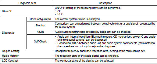
REG-AF
ON/OFF setting of the following items can be performed.
• AF
• REG
Diagnostic
Unit Configuration
The current system status is displayed.
Check item list


Monitor
A comparison check can be made of each actual vehicle signal and the signals
recognized by the system.
Check item list

Faults
Audio system malfunction detected by audio unit can be checked.
Error item list


NOTE
:
• OPEN: Open road
• SHORT-G: Short to ground
• SHORT-B: Short to battery
• SHORT-L: Short between the wiring
Self-Check
• Audio unit internal condition (Bluetooth module, CD mechanism, power IC and
audio unit front panel buttons)
can be diagnosed.
• Connection status between audio unit and audio system components (radio antenna, door speakers and microphone) can be diagnosed.
REGION SETTING
Reception frequency band (the reception area) setting of the radio can be set.
RADIO MONITOR
The reception state of the radio signal can be checked.
LCD CONTRAST
The contrast setting of the display can be adjusted.
Models without usb connection function
MODELS WITHOUT USB CONNECTION FUNCTION : Diagnosis Description
Self-diagnosis mode can check the following items.
• Display all icons and segments
• Display LCD
• Audio unit hardware/software/E2P versions
• Serial No.
• Model code
METHOD OF STARTING
1. Turn ignition switch to the ON position.
2. Turn the audio unit OFF.
3. With both “1” button and “5” button pressed, turn ON the audio system.
4. Audio unit display shows “SERVICE MODE”.

Icons, Segments and LCD Check 1. All display icons and segments will be illuminated for 2 seconds.
2. Press the “ENTER” switch to display LCD check segments pattern.

Version Check
1. Press the “ENTER” switch to enter version diagnostics. “Soft”
(audio software version) is displayed.

2. Press the “ENTER” switch again to display the “Hard” (audio hardware version).

3. Press the “ENTER” switch again to display the “E2P” (audio unit EEPROM version).

Serial No. Check
1. Press the “ENTER” switch again to display the audio unit serial
No.

Model Code Check
1. Press the “ENTER” switch again to display the audio unit model
code (vehicle EQ profile selection).

Finishing Self-diagnosis Mode Self-diagnosis mode is canceled when turning the ignition switch OFF.
 System
System Diagram
MODELS WITH USB CONNECTION FUNCTION
NOTE:
An antenna base integrated with radio antenna amp. is adopted.
MODELS WITHOUT USB CONNECTION FUNCTION
NOTE:
An antenna base integra ...
 Ecu diagnosis information
AUDIO UNIT
Reference Value
TERMINAL LAYOUT
PHYSICAL VALUES
• *1: Models with USB connection function
• *2: Models without USB connection function ...
Other materials:
ASCD steering switch
Component Function Check
1.CHECK ASCD STEERING SWITCH FUNCTION
1. Turn ignition switch ON.
2. Check the voltage between ECM harness connector terminals under the following
conditions.
Is the inspection result normal?
YES >> INSPECTION END
NO >> Go to EC-1011, "Diagnosis Pr ...
Ignition coil, spark plug and rocker cover
Exploded View
1. Ignition coil
2. Spark plug
3. Rocker cover
4. Hose cramp
5. PCV hose
6. PCV valve
7. O-ring
8. Gasket
9. Oil filler cap
10. O-ring
11. Camshaft position sensor (INT)
12. Camshaft position sensor (EXH)
13. Cramp
A. To intake manifold
: Always replace after e ...
Fuel filler lid opener
Exploded View
1. Fuel filler lid opener cable
2. Cable protector
3. Fuel filler lid lock assembly
4. Fuel filler lid assembly
5. Spring
6. Bumper rubber
: Clip
: Do not reuse
Fuel filler lid
FUEL FILLER LID : Removal and Installation
REMOVAL
1. Fully open fuel filler lid.
2. Remov ...