Nissan Juke Service and Repair Manual : Diagnosis and repair work flow
Work Flow
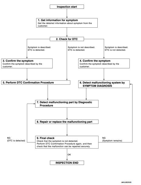
OVERALL SEQUENCE
DETAILED FLOW
1.GET INFORMATION FOR SYMPTOM
1. Get the detailed information from the customer about the symptom (the condition and the environment when the incident/malfunction occurred).
2. Check operation condition of the function that is malfunctioning.
>> GO TO 2.
2.CHECK FOR DTC
1. Check DTC for BCM.
2. Perform the following procedure if DTC is displayed.
- Erase DTC.
- Study the relationship between the cause detected by DTC and the symptom described by the customer.
3. Check related service bulletins for information.
Is any symptom described and any DTC detected? Symptom is described, DTC is displayed>>GO TO 3.
Symptom is described, DTC is not displayed>>GO TO 4.
Symptom is not described, DTC is displayed>>GO TO 5.
3.CONFIRM THE SYMPTOM
Confirm the symptom described by the customer.
Connect CONSULT-III to the vehicle in “DATA MONITOR” mode and check real-time diagnosis results.
Verify relation between the symptom and the condition when the symptom is detected.
>> GO TO 5.
4.CONFIRM THE SYMPTOM
Confirm the symptom described by the customer.
Connect CONSULT-III to the vehicle in “DATA MONITOR ” mode and check real-time diagnosis results.
Verify relation between the symptom and the condition when the symptom is detected.
>> GO TO 6.
5.PERFORM DTC CONFIRMATION PROCEDURE
Perform DTC Confirmation Procedure for the displayed DTC, and then check that DTC is detected again.
If two or more DTCs are detected, refer to BCS-140, "DTC Inspection Priority Chart" (BCM) and determine trouble diagnosis order.
Is DTC detected? YES >> GO TO 7.
NO >> Refer to GI-42, "Intermittent Incident".
6.DETECT MALFUNCTIONING SYSTEM BY SYMPTOM DIAGNOSIS
Detect malfunctioning system according to Symptom Diagnosis based on the confirmed symptom in step 4.
>> GO TO 7.
7.DETECT MALFUNCTIONING PART BY DIAGNOSTIC PROCEDURE
Inspect according to Diagnostic Procedure of the system.
NOTE
:
The Diagnostic Procedure is described based on open circuit inspection. A short circuit inspection is also required for the circuit check in the Diagnostic Procedure.
>> GO TO 8.
8.REPAIR OR REPLACE THE MALFUNCTIONING PART
1. Repair or replace the malfunctioning part.
2. Reconnect parts or connectors disconnected during Diagnostic Procedure again after repair and replacement.
3. Check DTC. If DTC is displayed, erase it.
>> GO TO 9.
9.FINAL CHECK
When DTC was detected in step 9, perform DTC Confirmation Procedure or Component Function Check again, and then check that the malfunctions have been fully repaired.
When symptom was described by the customer, refer to the confirmed symptom in step 3 or 4, and check that the symptom is not detected.
Are all malfunctions corrected? NO (DTC is detected)>>GO TO 7.
NO (Symptom remains)>>GO TO 6.
YES >> INSPECTION END
 Basic inspection
...
 Keyfob id registration
Description
Perform the following procedure after BCM is replaced or when new keyfob ID
is registered
NOTE:
When registering the keyfob ID, perform only one procedure to simultaneously
register ...
Other materials:
B2601 shift position
DTC Logic
DTC DETECTION LOGIC
NOTE:
• If DTC B2601 is displayed with DTC U1000, first perform the trouble diagnosis
for DTC U1000. Refer to
BCS-83, "DTC Logic".
• If DTC B2601 is displayed with DTC U1010, first perform the trouble diagnosis
for DTC U1010. Refer to
BCS-84, "D ...
Super lock does not operatE
All door
ALL DOOR : Diagnosis Procedure
1.CHECK SUPER LOCK ACTUATOR
Check front driver side super lock actuator.
Refer to DLK-407, "DRIVER SIDE : Component Function Check".
Is the inspection result normal?
YES >> GO TO 2.
NO >> Repair or replace the malfunctioning ...
Diagnosis system (BCM)
Common item
COMMON ITEM : CONSULT-III Function (BCM - COMMON ITEM)
APPLICATION ITEM
CONSULT-III performs the following functions via CAN communication with BCM.
SYSTEM APPLICATION
BCM can perform the following functions for each system.
NOTE:
It can perform the diagnosis modes except the ...