Nissan Juke Service and Repair Manual : CVT shift selector
Exploded View
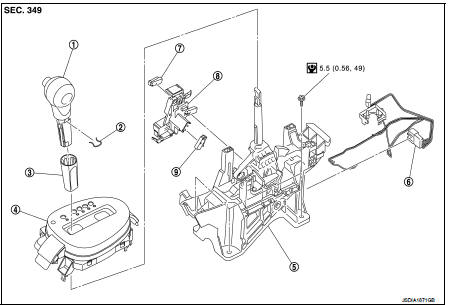
1. Selector lever knob
2. Lock pin
3. Knob cover
4 Position indication panel
5. CVT shift selector assembly
6. CVT shift lock unit
7. Key interlock rod*
8. Indicator lamp
 :N·m (kg-m, it-lb)
*: Without push engine starter
Removal and Installation
REMOVAL
CAUTION:
Always apply the parking brake before performing removal and installation.
1. Disconnect battery cable from negative terminal. Refer to PG-124, "Removal and Installation".
2. Shift the selector lever to “N” position.
3. Remove the center console. Refer to IP-23, "Removal and Installation".
4. Disconnect the CVT shift selector connector.
5. Shift the selector lever to “P” position.
6. Remove the key interlock cable from the CVT shift selector assembly. Refer to TM-276, "Removal and Installation" (Without push stater system).
7. Remove the control cable from the CVT shift selector assembly. Refer to TM-273, "Removal and Installation".
8. Remove the CVT shift selector assembly.
INSTALLATION
Note the following, and install in the reverse order of removal.
• When connecting the control cable (1) to the CVT shift selector assembly (2), face the grooved surface of the rib (A) up and insert the control cable until it stops.

Disassembly and Assembly
DISASSEMBLY
1. Slide the selector lever knob cover (1) down.
CAUTION:
Never damage the knob cover.
2. Pull out the lock pin (2).
3. Pull the selector lever knob (3) and knob cover upwards to remove them.
4. Remove the position lamp.

5. Disengage the hooks (A) (4 locations), and lift up the position indication panel (1) to separate it from the CVT shift selector assembly (2).
CAUTION:
Never damage the CVT shift selector assembly.

6. Shift the selector lever to “N” position.
7. Remove the shift lock unit from the CVT shift selector assembly.

INSTALLATION
Note the following, and install in the reverse order of removal.
• Follow the procedure below and place the selector knob onto the CVT shift selector.
1. Install the lock pin (2) onto the selector lever knob (3).
2. Install the knob cover (1) onto the selector lever knob.
3. Press the selector lever knob onto the selector lever until it clicks.
CAUTION:
• When pressing the selector lever knob onto the selector
lever, never press the selector lever knob button.
• Never strike the selector lever knob to press it into place.

• Follow the procedure below and press the shift lock unit onto the CVT shift selector.
1. Connect the connectors.
2. Install the shift lock unit.
Inspection
INSPECTION AFTER INSTALLATION
Check the CVT position. If a malfunction is found, adjust the CVT position. Refer to TM-194, "Inspection and Adjustment".

 Control cable
Exploded View
1. Control cable
2. Lock plate
3. Transaxle assembly
4. Bracket A
5. Bracket B
6. CVT shift selector assembly
A: Manual lever B: Grommet
: N·m (kg-m, ft-lb)
: N·m (kg-m, i ...
Other materials:
S terminal circuit
Description
The starter motor magnetic switch is supplied with power when the ignition
switch is turned to the START position
while the selector lever is in the P or N position for CVT models or the clutch
pedal is depressed for M/T
models.
Diagnosis Procedure
CAUTION:
Perform diagnosis un ...
Diagnosis system (audio unit)
Models with usb connection function
MODELS WITH USB CONNECTION FUNCTION : On Board Diagnosis Function
Self-diagnosis mode can check the following items.
METHOD OF STARTING
1. Start the engine.
2. Turn OFF audio.
3. While pressing the “SET UP” switch, turn the MENU dial counterclockwise
3 cl ...
U1000 can comm circuit
Description
CAN (Controller Area Network) is a serial communication line for real time
applications. It is an on-board multiplex
communication line with high data communication speed and excellent error
detection ability. A modern
vehicle is equipped with many ECMs, and each control unit shar ...