Nissan Juke Service and Repair Manual : C1113, C1145, C1146 yaw rate/side/decel g sensor
DTC Logic
DTC DETECTION LOGIC

DTC CONFIRMATION PROCEDURE
1.PRECONDITIONING
If “DTC CONFIRMATION PROCEDURE” has been previously conducted, always turn ignition switch OFF and wait at least 10 seconds before conducting the next test.
>> GO TO 2.
2.CHECK DTC DETECTION
 With CONSULT-III.
1. Turn the ignition switch OFF to ON.
2. Perform self-diagnosis for “ABS”.
Is DTC “C1113” “C1145” or “C1146” detected? YES >> Proceed to BRC-165, "Diagnosis Procedure".
NO >> INSPECTION END
Diagnosis Procedure
1.CHECK ABS ACTUATOR AND ELECTRIC UNIT (CONTROL UNIT) POWER SUPPLY SYSTEM
Check ABS actuator and electric unit (control unit) power supply system. Refer to BRC-205, "Diagnosis Procedure".
Is the inspection result normal? YES >> GO TO 2.
NO >> Repair or replace error-detected parts.
2.CHECK CONNECTOR
1. Turn ignition switch OFF.
2. Check ABS actuator and electric unit (control unit) harness connector for disconnection or looseness.
3. Check yaw rate/side/decel G sensor harness connector for disconnection or looseness.
Is the inspection result normal? YES >> GO TO 4.
NO >> Repair or replace error-detected parts, securely lock the connector, and GO TO 3.
3.PERFORM SELF-DIAGNOSIS
Perform self-diagnosis for “ABS” again.
Is DTC“C1113”, “C1145” or “C1146” detected? YES >> GO TO 4.
NO >> INSPECTION END
4.CHECK YAW RATE/SIDE/DECEL G SENSOR POWER SUPPLY CIRCUIT
1. Turn ignition switch OFF.
2. Disconnect ABS actuator and electric unit (control unit) harness connector.
3. Disconnect yaw rate/side/decel G sensor harness connector.
4. Check continuity between yaw rate/side/decel G sensor harness connector and ABS actuator and electric unit (control unit) harness connector.

Is the inspection result normal? YES >> GO TO 5.
NO >> Repair or replace error-detected parts.
5.CHECK YAW RATE/SIDE/DECEL G SENSOR GROUND SIRCUIT
Check continuity between yaw rate/side/decel G sensor harness connector and ABS actuator and electric unit (control unit) harness connector.

Is the inspection result normal? YES >> GO TO 6.
NO >> Repair or replace error-detected parts.
6.CHECK YAW RATE/SIDE/DECEL G SENSOR SIGNAL CIRCUIT
Check continuity between yaw rate/side/decel G sensor harness connector and ABS actuator and electric unit (control unit) harness connector.

Is the inspection result normal? YES >> GO TO 7.
NO >> Repair or replace error-detected parts.
7.CHECK YAW RATE/SIDE/DECEL G SENSOR CIRCUIT
Check continuity between each terminals of yaw rate/side/decel G sensor harness connector.

Is the inspection result normal? YES >> GO TO 8.
NO >> Repair or replace error-detected parts.
8.CHECK YAW RATE/SIDE/DECEL G SENSOR 1
With CONSULT-III.
1. Connect yaw rate/side/decel G sensor harness connector.
2. Connect ABS actuator and electric unit (control unit) harness connector.
3. Turn the ignition switch ON.
4. Select “ABS”, “DATA MONITOR” and “DECEL G-SEN” in order.
5. Move yaw rate/side/decel G sensor as shown in the figure to check the output of before and after moving the sensor.
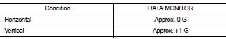

Is the inspection result normal? YES >> GO TO 9.
NO >> Replace yaw rate/side/decel G sensor. Refer to BRC- 235, "Removal and Installation".
9.CHECK YAW RATE/SIDE/DECEL G SENSOR 2
1. Turn ignition switch OFF.
2. Connect following terminals between yaw rate/side/decel G sensor and harness connector.

3. Turn ignition switch ON.
CAUTION:
Never start the engine.
4. Check voltage between yaw rate/side/decel G sensor harness connector terminals.
CAUTION:
Never short out the terminals while measuring voltages.

Is the inspection result normal? YES >> Replace ABS actuator end electric unit (control unit). Refer to BRC-233, "Removal and Installation".
NO >> Replace yaw rate/side/decel G sensor. Refer to BRC-235, "Removal and Installation".
 C1111 ABS motor, motor relay system
DTC Logic
DTC DETECTION LOGIC
DTC CONFIRMATION PROCEDURE
1.PRECONDITIONING
If “DTC CONFIRMATION PROCEDURE” has been previously conducted, always turn
ignition switch OFF and
wait at least 10 ...
 C1115 wheel sensor
DTC Logic
DTC CONFIRMATION PROCEDURE
1.PRECONDITIONING
If “DTC CONFIRMATION PROCEDURE” has been previously conducted, always turn
ignition switch OFF and
wait at least 10 seconds before conduc ...
Other materials:
Ignition coil, spark plug and rocker cover
Exploded View
1. Rocker cover protector
2. O-ring
3. PCV control valve
4. PCV hose
5. Clamp
6. Rocker cover gasket
7. Rocker cover
8. Clamp
9. PCV hose
10. Oil filler cap
11. Spark plug
12. Ignition coil
A. To air duct assembly
B.Tightening must be done following
the instal ...
Precaution for Supplemental Restraint System (SRS) "AIR BAG" and "SEAT BELT
PRE-TENSIONER"
The Supplemental Restraint System such as “AIR BAG” and “SEAT BELT PRE-TENSIONER”,
used along
with a front seat belt, helps to reduce the risk or severity of injury to the
driver and front passenger for certain
types of collision. Information necessary to service the system safely is
include ...
General maintenance
During the normal day-to-day operation of the vehicle, general maintenance should
be performed regularly as prescribed in this section. If you detect any unusual
sounds, vibrations or smell, be sure to check for the cause or have a NISSAN dealer
do it promptly. In addition, you should notify a ...