Nissan Juke Service and Repair Manual : Brake piping
Front : Exploded View
WITHOUT ESP

1. Brake tube
2. ABS actuator and electric unit (control
unit)
3. Connector
4. Connector bracket
5. Master cylinder assembly
6. Brake booster
7. Lock plate
8. Brake hose
9. Union bolt
10. Copper washer
A. To rear brake tube
 : N·m (kg-m, ft-lb)
 : N·m (kg-m, in-lb)
 : Always replace after every
disassembly.
WITH ESP
MR16DDT, HR16DE

1. Brake tube
2. Pressure sensor connector
3. Pressure sensor
4. ABS actuator and electric unit (control
unit)
5. Connector
6. Connector bracket
7. Master cylinder assembly
8. Brake booster
9. Lock plate
10. Brake hose
11. Union bolt
12. Copper washer
A. To rear brake tube
 : N·m (kg-m, ft-lb)
 : N·m (kg-m, in-lb)
 : Always replace after every
disassembly.
K9K

1. Brake tube
2. ABS actuator and electric unit (control
unit)
3. Connector
4. Connector bracket
5. Master cylinder assembly
6. Brake booster
7. Lock plate
8. Brake hose
9. Union bolt
10. Copper washer
A. To rear brake tube
 : N·m (kg-m, ft-lb)
 : N·m (kg-m, in-lb)
 : Always replace after every
disassembly.
Front : Hydraulic Piping
WITHOUT ESP

1. ABS actuator and electric unit (control
unit)
2. Front disc brake
3. Master cylinder assembly
4. Brake booster
5. Connector
6. Rear disc brake
A. Brake tube
B. Brake hose
 : Flare nut
 : Union bolt
WITH ESP
2WD
MR16DDT, HR16DE

1. ABS actuator and electric unit (control
unit)
2. Front disc brake
3. Pressure sensor
4. Master cylinder assembly
5. Brake booster
6. Connector
7. Rear disc brake
A. Brake tube
B. Brake hose
: Flare nut
Union bolt
K9K

1. ABS actuator and electric unit (control
unit)
2. Front disc brake
3. Master cylinder assembly
4. Brake booster
5. Connector
6. Rear disc brake
A. Brake tube
B. Brake hose
: Flare nut
: Union bolt
4WD

1. ABS actuator and electric unit (control
unit)
2. Front disc brake
3. Pressure sensor
4. Master cylinder assembly
5. Brake booster
6. Connector
7. Rear disc brake
A. Brake tube
B. Brake hose
: Flare nut
: Union bolt
Front : Removal and Installation
REMOVAL
CAUTION:
• Never spill or splash brake fluid on painted surfaces. Brake fluid may
seriously damage paint. Wipe it
off immediately and wash with water if it gets on a painted surface. For brake
component parts,
never wash them with water.
• Never depress the brake pedal while removing the brake hose or brake tube. If this is not complied with, brake fluid may splash.
1. Remove tires.
2. Drain brake fluid. Refer to BR-12, "Draining".
3. Loosen the flare nut (1) with a flare nut wrench (A) and separate the brake tube (2) from the brake hose (3).
CAUTION:
• Never scratch the flare nut and the brake tube.
• Never bend sharply, twist or strongly pull out the brake hoses and tubes.
• Cover open end of brake tubes and hoses when disconnecting to prevent entrance of dirt.

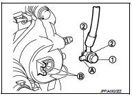
4. Remove the union bolt (1) and copper washers (2), and remove the brake hose (3) from the brake caliper assembly.
5. Remove the lock plate (4) and remove the brake hose.

INSTALLATION
CAUTION:
• Never spill or splash brake fluid on painted surfaces. Brake fluid may
seriously damage paint. Wipe it
off immediately and wash with water if it gets on a painted surface. For brake
component parts,
never wash them with water.
• Never depress the brake pedal while removing the brake hose or brake tube. If this is not complied with, brake fluid may splash.
1. Assemble the union bolt (1) and the copper washer (2) to the brake hose.
CAUTION:
Never reuse the copper washer.
2. Align the brake hose pin (A) with the brake caliper assembly projection (B), and tighten the union bolt (1) to the specified torque.
3. Install the brake tube (2) to the brake hose (1), temporarily tighten the flare nut (3) by hand until it does not rotate further, and fix the brake hose to the bracket (5) with the lock plate (4).
CAUTION:
Check that all brake hoses and brake tubes are not twisted
and bent.

4. Tighten the flare nut to the specified torque with a flare nut torque wrench (A).
CAUTION
:
Never scratch the flare nut and the brake tube.
5. Refill with new brake fluid and perform the air bleeding. Refer to BR-13, "Bleeding Brake System".
CAUTION:
Never reuse drained brake fluid.
6. Install tires. Refer to WT-7, "Exploded View".
7. Perform inspection after installation. Refer to BR-30, "FRONT : Inspection".

Front : Inspection
INSPECTION AFTER INSTALLATION
1. Check the brake hoses and tubes for the following: no scratches; no twist and deformation; no interference with other components when steering the steering wheel; no looseness at connections.
2. Depress the brake pedal with a force of 785 N (80 kg, 176 lb) and hold down the pedal for approximately 5 seconds with the engine running. Check for any fluid leakage.
CAUTION
:
Retighten the applicable connection to the specified torque and repair any
abnormal (damaged,
worn or deformed) part if any brake fluid leakage is present.
Rear : Exploded View
2WD (MR16DDT, HR16DE)

1. Brake tube
2. Brake hose A
3. Lock plate
4. Brake hose bracket
5. Union bolt
6. Brake hose B
7. Copper washer
A. To connector
 : N·m (kg-m, ft-lb)
 : N·m (kg-m, in-lb)
 : Always replace after every
disassembly.
2WD (K9K)

1. Brake tube
2. Brake hose A
3. Lock plate
4. Brake hose bracket
5. Union bolt
6. Brake hose B
7. Copper washer
A. To connector
: N·m (kg-m, ft-lb)
: N·m (kg-m, in-lb)
: Always replace after every
disassembly.
4WD

1. Brake tube
2. Brake hose A
3. Lock plate
4. Brake hose bracket
5. Brake hose B
6. Union bolt
7. Copper washer
A. To connector
: N·m (kg-m, ft-lb)
: N·m (kg-m, in-lb)
: Always replace after every
disassembly.
Rear : Hydraulic Piping
WITHOUT ESP

1. ABS actuator and electric unit (control
unit)
2. Front disc brake
3. Master cylinder assembly
4. Brake booster
5. Connector
6. Rear disc brake
A. Brake tube
B. Brake hose
 : Flare nut
 : Union bolt
WITH ESP
2WD
MR16DDT, HR16DE

1. ABS actuator and electric unit (control
unit)
2. Front disc brake
3. Pressure sensor
4. Master cylinder assembly
5. Brake booster
6. Connector
7. Rear disc brake
A. Brake tube
B. Brake hose
 : Flare nut
 : Union bolt
K9K

1. ABS actuator and electric unit (control
unit)
2. Front disc brake
3. Master cylinder assembly
4. Brake booster
5. Connector
6. Rear disc brake
A. Brake tube
B. Brake hose
: Flare nut
Union bolt
4WD

1. ABS actuator and electric unit (control
unit)
2. Front disc brake
3. Pressure sensor
4. Master cylinder assembly
5. Brake booster
6. Connector
7. Rear disc brake
A. Brake tube
B. Brake hose
: Flare nut
: Union bolt
Rear : Removal and Installation
REMOVAL
2WD
CAUTION
:
• Never spill or splash brake fluid on painted surfaces. Brake fluid may
seriously damage paint. Wipe it
off immediately and wash with water if it gets on a painted surface. For brake
component parts,
never wash them with water.
• Never depress the brake pedal while removing the brake hose or brake tube. If this is not complied with, brake fluid may splash.
1. Remove tires.
2. Drain brake fluid. Refer to BR-12, "Draining".
3. Loosen the flare nut (1) with a flare nut wrench (A) and separate the brake tube (2) from the brake hose A (3).
CAUTION:
• Never scratch the flare nut and the brake tube.
• Never bend sharply, twist or strongly pull out the brake hoses and tubes.
• Cover open end of brake tubes and hoses when disconnecting to prevent entrance of dirt.
4. Remove the lock plate (4) and remove the brake hose A.

5. Loosen the flare nut (1) with a flare nut wrench (A) and separate the brake tube (2) from the hose B (3).
CAUTION:
• Never scratch the flare nut and the brake tube.
• Never bend sharply, twist or strongly pull out the brake hoses and tubes.
• Cover open end of brake tubes and hoses when disconnecting to prevent entrance of dirt.
6. Remove the lock plate (4) from brake hose bracket (5).

7. Remove the union bolt (1) and copper washers (2), and remove the brake hose B (3) from the brake caliper assembly.

4WD
CAUTION:
• Never spill or splash brake fluid on painted surfaces. Brake fluid may
seriously damage paint. Wipe it
off immediately and wash with water if it gets on a painted surface. For brake
component parts,
never wash them with water.
• Never depress the brake pedal while removing the brake hose or brake tube. If this is not complied with, brake fluid may splash.
1. Remove tires.
2. Drain brake fluid. Refer to BR-12, "Draining".
3. Loosen the flare nut (1) with a flare nut wrench (A) and separate the brake tube (2) from the hose A (3).
CAUTION:
• Never scratch the flare nut and the brake tube.
• Never bend sharply, twist or strongly pull out the brake hoses and tubes.
• Cover open end of brake tubes and hoses when disconnecting to prevent entrance of dirt.
4. Remove the lock plate (4) and remove the brake hose A.

5. Loosen the flare nut (1) with a flare nut wrench (A) and separate the brake tube (2) from the hose B (3).
CAUTION:
• Never scratch the flare nut and the brake tube.
• Never bend sharply, twist or strongly pull out the brake hoses and tubes.
• Cover open end of brake tubes and hoses when disconnecting to prevent entrance of dirt.
6. Remove the lock plate (4) from brake hose bracket (5).

7. Remove the union bolt (1) and copper washers (2), and remove the brake hose B (3) from the brake caliper assembly.

INSTALLATION
2WD
CAUTION:
• Never spill or splash brake fluid on painted surfaces. Brake fluid may
seriously damage paint. Wipe it
off immediately and wash with water if it gets on a painted surface. For brake
component parts,
never wash them with water.
• Never depress the brake pedal while removing the brake hose or brake tube. If this is not complied with, brake fluid may splash.
1. Assemble the union bolt (1) and the copper washer (2) to the brake hose B.
CAUTION:
Never reuse the copper washer.
2. Align the brake hose B L-pin (A) with the brake caliper assembly hole (B), and tighten the union bolt (1) to the specified torque.

3. Install the brake tube (2) to the brake hose B (1), temporarily tighten the flare nut (3) by hand until it does not rotate further, and fix the brake hose B to the brake hose bracket (5) with the lock plate (4).
CAUTION:
Check that all brake hoses and brake tubes are not twisted
and bent.

4. Tighten the flare nut to the specified torque with a flare nut torque wrench (A).
CAUTION:
Never scratch the flare nut and the brake tube.

5. Install the brake tube (2) to the brake hose A (1), temporarily tighten the flare nut (3) by hand until it does not rotate further, and fix the brake hose with the lock plate (4).
CAUTION:
Check that all brake hoses and brake tubes are not twisted
and bent.

6. Tighten the flare nut to the specified torque with a flare nut torque wrench (A).
CAUTION:
Never scratch the flare nut and the brake tube.
7. Refill with new brake fluid and perform the air bleeding. Refer to BR-13, "Bleeding Brake System".
CAUTION:
Never reuse drained brake fluid.
8. Install tires. Refer to WT-7, "Exploded View".
9. Perform inspection after installation. Refer to BR-39, "REAR : Inspection".

4WD
CAUTION:
• Never spill or splash brake fluid on painted surfaces. Brake fluid may
seriously damage paint. Wipe it
off immediately and wash with water if it gets on a painted surface. For brake
component parts,
never wash them with water.
• Never depress the brake pedal while removing the brake hose or brake tube. If this is not complied with, brake fluid may splash.
1. Assemble the union bolt (1) and the copper washer (2) to the brake hose B.
CAUTION
:
Never reuse the copper washer.
2. Align the brake hose B L-pin (A) with the brake caliper assembly hole (B), and tighten the union bolt (1) to the specified torque.

3. Install the brake tube (2) to the brake hose B (1), temporarily tighten the flare nut (3) by hand until it does not rotate further, and fix the brake hose B to the brake hose bracket (5) with the lock plate (4).
CAUTION:
Check that all brake hoses and brake tubes are not twisted
and bent
.

4. Tighten the flare nut to the specified torque with a flare nut torque wrench (A).
CAUTION:
Never scratch the flare nut and the brake tube.

5. Install the brake tube (2) to the brake hose A (3), temporarily tighten the flare nut (1) by hand until it does not rotate further, and fix the brake hose A to the bracket with the lock plate (4).
CAUTION:
Check that all brake hoses and brake tubes are not twisted
and bent.

6. Tighten the flare nut to the specified torque with a flare nut torque wrench (A).
CAUTION:
Never scratch the flare nut and the brake tube.
7. Refill with new brake fluid and perform the air bleeding. Refer to BR-13, "Bleeding Brake System".
CAUTION:
Never reuse drained brake fluid.
8. Install tires. Refer to WT-7, "Exploded View".
9. Perform inspection after installation. Refer to BR-39, "REAR : Inspection".

Rear : Inspection
INSPECTION AFTER INSTALLATION
1. Check the brake hoses and tubes for the following: no scratches; no twist and deformation; no looseness at connections.
2. Depress the brake pedal with a force of 785 N (80kg, 176 lb) and hold down the pedal for approximately 5 seconds with the engine running. Check for any fluid leakage.
CAUTION
:
Retighten the applicable connection to the specified torque and repair any
abnormal (damaged,
worn or deformed) part if any brake fluid leakage is present.
 Brake pedal
Exploded View
WITHOUT ESP
1. Clevis pin
2. Brake pedal assembly
3. Brake pedal pad
4. Stop lamp switch
5. Clip
6. Snap pin
: Apply multi-purpose grease.
: N·m (kg-m, ft-lb)
WITH ESP
...
 Brake master cyl
Exploded View
2WD
1. Reservoir cap
2. Oil strainer
3. Reservoir tank
4. Cylinder body
5. Pin
6. O-ring
7. Grommet
: Apply polyglycol ether based
lubricant.
: Apply brake fluid.
: N· ...
Other materials:
Lift gate
WARNING
• Always be sure the lift gate has been closed securely to prevent it from
opening while driving.
• Do not drive with the lift gate open.
This could allow dangerous exhaust gases to be drawn into the vehicle.
See “Exhaust gas (carbon monoxide)” of this manual.
• Do not leave chi ...
Precaution for Supplemental Restraint System (SRS) "AIR BAG" and "SEAT BELT
PRE-TENSIONER"
The Supplemental Restraint System such as “AIR BAG” and “SEAT BELT PRE-TENSIONER”,
used along
with a front seat belt, helps to reduce the risk or severity of injury to the
driver and front passenger for certain
types of collision. Information necessary to service the system safely is
include ...
B2602 shift position
DTC Logic
DTC DETECTION LOGIC
NOTE:
• If DTC B2602 is displayed with DTC U1000, first perform the trouble diagnosis
for DTC U1000. Refer to
BCS-83, "DTC Logic".
• If DTC B2602 is displayed with DTC U1010, first perform the trouble diagnosis
for DTC U1010. Refer to
BCS-84, "D ...