Nissan Juke Service and Repair Manual : Brake pedal position switch
Component Function Check
1.CHECK BRAKE PEDAL POSITION SWITCH FUNCTION
 With CONSULT-III
1. Turn ignition switch ON.
2. Select “BRAKE SW1” in “DATA MONITOR” mode of “ENGINE” using CONSULT-III.
3. Check “BRAKE SW1” indication as per the following conditions.

 Without CONSULT-III
1. Turn ignition switch ON.
2. Check the voltage between ECM harness connector terminals as per the following.

Is the inspection result normal? YES >> INSPECTION END
NO >> Proceed to EC-425, "Diagnosis Procedure".
Diagnosis Procedure
1.CHECK BRAKE PEDAL POSITION SWITCH POWER SUPPLY
1. Turn ignition switch OFF.
2. Disconnect brake pedal position switch harness connector.
3. Turn ignition switch ON.
4. Check the voltage between brake pedal position switch harness connector and ground.

*1: LHD models or RHD with CVT models *2: RHD with M/T models
Is the inspection result normal? YES >> GO TO 2.
NO >> Perform the trouble diagnosis for power supply circuit.
2.CHECK BRAKE PEDAL POSITION SWITCH INPUT SIGNAL CIRCUIT
1. Turn ignition switch OFF.
2. Disconnect ECM harness connector.
3. Check the continuity between brake pedal position switch harness connector and ECM harness connector.
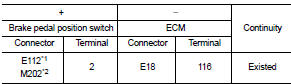
*1: LHD models or RHD with CVT models *2: RHD with M/T models
4. Also check harness for short to ground and to power.
Is the inspection result normal? YES >> GO TO 3.
NO >> Repair or replace error-detected parts.
3.CHECK BRAKE PEDAL POSITION SWITCH
Check the brake pedal position switch. Refer to EC-426, "Component Inspection (Brake Pedal Position Switch)" Is the inspection result normal? YES >> Check intermittent incident. Refer to GI-42, "Intermittent Incident".
NO >> Replace brake pedal position switch. Refer to BR-20, "Exploded View" (LHD) or BR-88, "Exploded View" (RHD)
Component Inspection (Brake Pedal Position Switch)
1.CHECK BRAKE PEDAL POSITION SWITCH-I
1. Turn ignition switch OFF.
2. Disconnect brake pedal position harness connector.
3. Check the continuity between brake pedal position switch terminals as per the following conditions.

Is the inspection result normal? YES >> INSPECTION END
NO >> GO TO 2.
2.CHECK BRAKE PEDAL POSITION SWITCH-II
1. Adjust brake pedal position switch installation. Refer to BR-9, "Inspection and Adjustment" (LHD) or BR- 77, "Inspection and Adjustment" (RHD).
2. Check the continuity between brake pedal position switch terminals as per the following conditions.

Is the inspection result normal? YES >> INSPECTION END
NO >> Replace brake pedal position switch. Refer to BR-20, "Exploded View" (LHD) or BR-88, "Exploded View" (RHD).
 Refrigerant pressure sensor
Component Function Check
1.CHECK REFRIGERANT PRESSURE SENSOR OVERALL FUNCTION
1. Start engine and warm it up to normal operating temperature.
2. Turn A/C switch and blower fan switch ON.
3. Check ...
 Clutch pedal position switch
Component Function Check
1.CHECK FOR CLUTCH PEDAL POSITION SWITCH FUNCTION
1. Turn ignition switch ON.
2. Check the voltage between ECM harness connector and ground.
Is the inspection result nor ...
Other materials:
B2614 ACC relay circuit
DTC Logic
DTC DETECTION LOGIC
DTC CONFIRMATION PROCEDURE
1.PERFORM DTC CONFIRMATION PROCEDURE
1. Turn the power supply position to ACC under the following conditions, and
wait for 2 second or more.
CVT models
- Selector lever is in the P or N position
- Do not depress brake pedal
M/T m ...
Vehicle information
BODY EXTERIOR PAINT COLOR
Body Exterior Paint Color
FOR 2WD MODELS
NOTE:
• S: Solid
• 2S: Solid + Clear
• CS: Color clear solid
• M: Metallic
• P: 2-Coat pearl
• 3P: 3-Coat pearl
• FPM: Iron oxide pearl
• RPM: Multi flex color
• TM: Micro titanium metallic
• PM: Pearl metallic
FOR ...
How to use touch screen
CAUTION
• The glass screen on the liquid crystal display may break if it is hit with
a hard or sharp object. If the glass screen breaks, do not touch it.
Doing so could result in an injury.
• To clean the display, never use a rough cloth, alcohol, benzine, thinner or any
kind of solvent or pa ...