Nissan Juke Service and Repair Manual : B26E8 clutch interlock switch
DTC Logic
NOTE
:
• If DTC B26E8 is displayed with DTC B210F, first perform the trouble diagnosis
for DTC B210F. Refer to
BCS-83, "DTC Logic".
• If DTC B26E8 is displayed with DTC B2110, first perform the trouble diagnosis for DTC B2110. Refer to BCS-84, "DTC Logic".
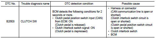
DTC DETECTION LOGIC
DTC CONFIRMATION PROCEDURE
1.PERFORM DTC CONFIRMATION PROCEDURE 1
1. Turn ignition switch ON and wait 2 seconds or more under the following conditions.
- Shift lever: In the neutral position.
- Clutch pedal: Depressed 2. Check DTC in “Self Diagnostic Result” mode of “BCM” using CONSULT-III.
Is DTC detected? YES >> Go to SEC-113, "Diagnosis Procedure".
NO >> GO TO 2.
2.PERFORM DTC CONFIRMATION PROCEDURE 2
1. Release clutch pedal and wait 2 seconds or more.
2. Check DTC in “Self Diagnostic Result” mode of “BCM” using CONSULT-III.
Is DTC detected? YES >> Go to SEC-113, "Diagnosis Procedure".
NO >> INSPECTION END
Diagnosis Procedure
1.INSPECTION START
Perform inspection in accordance with procedure that confirms DTC.
Which procedure confirms DTC? DTC confirmation procedure 1>>GO TO 2.
DTC confirmation procedure 2>>GO TO 3.
2.CHECK CLUTCH PEDAL POSITION SWITCH CIERCUIT
Refer to EC-427, "Component Function Check" (MR16DDT), EC-771, "Component Function Check" (HR16DE), or EC-980, "DTC Logic" (K9K).
Is the inspection result normal? YES >> GO TO 8.
NO >> Repair or replace the malfunctioning parts.
3.CHECK CLUTCH INTERLOCK SWITCH POWER SUPPLY
1. Turn ignition switch OFF.
2. Disconnect clutch interlock switch connector 3. Check voltage between clutch interlock switch harness connector and ground.

Is the inspection result normal? YES >> GO TO 4.
NO-1 >> Check 10 A fuse [No. 13, located in the fuse block (J/B)] NO-2 >> Check harness for open or short between clutch interlock switch and fuse.
4.CHECK CLUTCH INTERLOCK SWITCH SIGNAL
1. Connect clutch interlock switch connector.
2. Check voltage between BCM harness connector and ground.

Is the inspection result normal? YES >> GO TO 8.
NO >> GO TO 5.
5.CHECK CLUTCH INTERLOCK SWITCH SIGNAL CIRCUIT
1. Disconnect clutch interlock switch connector.
2. Disconnect BCM connector.
3. Check continuity between clutch interlock switch harness connector and BCM harness connector.

4. Check continuity between clutch interlock switch harness connector and ground.

Is the inspection result normal? YES >> GO TO 6.
NO >> Repair or replace harness.
6.CHECK CLUTCH INTERLOCK SWITCH
Refer to SEC-115, "Component Inspection".
Is the inspection result normal? YES >> GO TO 7.
NO >> Replace clutch interlock switch. Refer to CL-16, "LHD : Removal and Installation" (LHD) or CL-18, "RHD : Removal and Installation" (RHD).
7.CHECK INTERMITTENT INCIDENT
Refer to GI-42, "Intermittent Incident".
>> INSPECTION END
8.REPLACE BCM
1. Replace BCM. Refer to BCS-93, "Removal and Installation".
2. Perform initialization of BCM and reregistration of all Intelligent Key using CONSULT-III.
For initialization and reregistration procedures, refer to CONSULT-III Operation Manual NATS-IVIS/NVIS.
>> INSPECTION END
Component Inspection
1.CHECK CLUTCH INTERLOCK SWITCH
1. Turn ignition switch OFF.
2. Disconnect clutch interlock switch connector.
3. Check continuity between clutch interlock switch terminals.

Is the inspection result normal? YES >> INSPECTION END
NO >> Replace clutch interlock switch. Refer to CL-16, "LHD : Removal and Installation" (LHD) or CL-18, "RHD : Removal and Installation" (RHD).
 B2620 Park/neutral position switch
DTC Logic
DTC DETECTION LOGIC
DTC CONFIRMATION PROCEDURE
1.PERFORM DTC CONFIRMATION PROCEDURE
1. Turn ignition switch ON and wait 2 seconds or more under the following
conditions.
2. Set shif ...
 B26E9 steering status
DTC Logic
DTC DETECTION LOGIC
DTC CONFIRMATION PROCEDURE
1.PERFORM DTC CONFIRMATION PROCEDURE
1. Turn ignition switch ON.
2. Turn ignition switch OFF.
3. Press driver side door switch.
4. Tur ...
Other materials:
Commercial Service Tools
HFC-134a (R-134a) Service Tool and Equipment
• Never mix HFC-134a (R-134a) refrigerant and/or its specified lubricant with
CFC-12 (R-12) refrigerant and/
or its lubricant.
• Separate and non-interchangeable service equipment must be used for handling
each type of refrigerant/
lubricant.
• R ...
Manual air conditioner (if so equipped)
1. Air intake lever (Outside air circulation
/Air recirculation
)
2. Air flow control dial
3. Fan speed control dial
4. A/C (Air Conditioner) button
5. Temperature control dial
6. Rear window defroster button (See
“Rear window and outside mirror defroster switch” .)
To turn off the he ...
B2268 water temp
Description
The engine coolant temperature signal is transmitted from ECM to the
combination meter via CAN communication.
DTC Logic
DTC DETECTION LOGIC
Diagnosis Procedure
1.PERFORM SELF-DIAGNOSIS OF ECM
Perform “Self Diagnosis Result” of “ENGINE”, and repair or replace
malfunctioning pa ...