Nissan Juke Service and Repair Manual : B2108 steering lock relay
DTC Logic
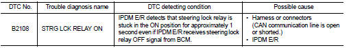
DTC DETECTION LOGIC
NOTE
:
If DTC B2108 is displayed with DTC U1000, first perform the trouble diagnosis
for DTC U1000. Refer to PCS-
30, "DTC Logic".
DTC CONFIRMATION PROCEDURE
1.PERFORM DTC CONFIRMATION PROCEDURE
1. Press push-button ignition switch under the following conditions and wait 1 second or more.
- Selector lever: In the P position - Brake pedal: Not depressed 2. Check DTC in “Self Diagnostic Result” mode of “IPDM E/R” using CONSULT-III.
Is DTC detected? YES >> Go to SEC-138, "Diagnosis Procedure".
NO >> INSPECTION END
Diagnosis Procedure
1.CHECK STEERING LOCK RELAY
Check voltage between IPDM E/R harness connector and ground.

Is the inspection result normal? YES >> GO TO 2.
NO >> Replace IPDM E/R. Refer to PCS-34, "Removal and Installation".
2.CHECK INTERMITTENT INCIDENT
Refer to GI-42, "Intermittent Incident".
>> INSPECTION END
 B20A0 cranking request circuit
DTC Logic
DTC DETECTION LOGIC
NOTE:
If DTC B20A0 is displayed with DTC U1000, first perform the trouble diagnosis
for DTC U1000. Refer to PCS-
30, "DTC Logic".
DTC CONFIRMATION PROC ...
 B2109 steering lock relay
DTC Logic
DTC DETECTION LOGIC
NOTE:
• If DTC B2109 is displayed with DTC U1000, first perform the trouble diagnosis
for DTC U1000. Refer to
PCS-30, "DTC Logic".
• When IPDM E/R power ...
Other materials:
LAN System can system (type 11)
DTC/CIRCUIT DIAGNOSIS
Main line between IPDM-E and DLC circuit
Diagnosis Procedure
1.CHECK CONNECTOR
1. Turn the ignition switch OFF.
2. Disconnect the battery cable from the negative terminal.
3. Check the following terminals and connectors for damage, bend and loose
connection (connector s ...
Heater and air conditioner
WARNING
• The air conditioner cooling function operates only when the engine
is running.
• Do not leave children or adults who would normally require the support of others
alone in your vehicle. Pets should not be left alone either. On hot, sunny days,
temperatures in a closed vehicle ...
A/C auto AMP.
Reference Value
CONSULT-III DATA MONITOR REFERENCE VALUES
*: “DUTY” is displayed, but voltage is indicated. Or unit is not displayed
but unit is (V).
TERMINAL LAYOUT
PHYSICAL VALUES
*: With K9K
Fail-safe
FAIL-SAFE FUNCTION
If a communication error exists between the A/C auto amp. a ...