Nissan Juke Service and Repair Manual : Air conditioner filter
Exploded View
LHD models

1. A/C unit assembly 2. Air conditioner filter 3. Filter cover
Removal and Installation (LHD models)
REMOVAL
1. Remove glove box assembly. Refer to IP-13, "Removal and Installation".
2. Remove filter cover (1), and then remove air conditioner filter (2) from A/C unit assembly.
CAUTION:
If the filter is deformed/damaged when removing, replace it
with a new one. Deformed/damaged filter may deteriorate
the dust collecting performance.

INSTALLATION
Note the following item, and install in the reverse order of removal.
CAUTION:
When installing, handle the filter with extreme care to avoid
deforming/damaging.
Removal and Installation (RHD models)
REMOVAL
NOTE
:
When removing air conditioner filter, visually check the operation through glove
box mask opening.
1. Open glove box lid. Remove glove box mask.
 : Pawl

2. Remove filter cover according to the numerical order as shown in the figure, while putting a hand through bottom of glove box and pressing pawl (A) of filter cover.
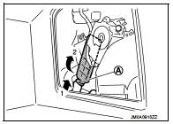
3. Pull out air conditioner filter from A/C unit assembly according to the numerical order as shown in the figure. Remove air conditioner filter through bottom of glove box.

CAUTION:
If the filter is deformed/damaged when removing, replace it with a new one.
Deformed/damaged filter
may deteriorate the dust collecting performance.
INSTALLATION
NOTE
:
When removing air conditioner filter, visually check the operation through glove
box mask opening.
CAUTION:
When installing, handle the filter with extreme care to avoid
deforming/damaging.
Replacement
Replace Air conditioner filter.
Refer to VTL-20, "Air Conditioner Filter".
 Blower motor
Exploded View
2WD models
1. A/C unit assembly
2. Fan control amp.*1
3. Blower fan resistor*2
4. Blower motor
5. Blower motor cover
• *1: Automatic air conditioner
• *2: Manual air conditi ...
 Service data and specifications (SDS)
Air Conditioner Filter
...
Other materials:
Steering does not lock
Description
Steering does not lock when door is open while ignition switch is OFF.
NOTE:
Before performing the diagnosis, check “Work Flow”. Refer to SEC-47, "Work
Flow".
Diagnosis Procedure
1.CHECK DOOR SWITCH
Check door switch.
Refer to DLK-87, "Component Function Check ...
Removal and Installation Procedure for CVT Unit Connector
REMOVAL
Rotate bayonet ring (1) counterclockwise, pull out CVT unit harness
connector (2) upward and remove it.
INSTALLATION
1. Align Δ marking on CVT unit harness connector terminal body
with marking on bayonet ring, insert CVT unit harness connector,
and then rotate bayonet ...
Blower fan resistor
Exploded View
1. A/C unit assembly
2. Blower fan resistor*1
3. Sub harness*1
4. Power transistor*2
5. Sub harness*2
6. Blower motor
• *1: Manual air conditioner
• *2: Automatic air conditioner
Removal and Installation
REMOVAL
1. Remove instrument panel assembly. Refer to IP-13, &quo ...