Nissan Juke Service and Repair Manual : P183A coupling temperature sensor right
DTC Logic
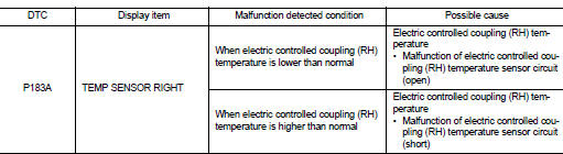
DTC DETECTION LOGIC
DTC CONFIRMATION PROCEDURE
1.PRECONDITIONING
If “DTC CONFIRMATION PROCEDURE” has been previously conducted, always turn ignition switch OFF and wait at least 10 seconds before conducting the next test.
>> GO TO 2.
2.DTC REPRODUCTION PROCEDURE
 With CONSULT-III
1. Turn the ignition switch OFF to ON.
2. Perform self-diagnosis for “ALL MODE AWD/4WD”.
Is DTC “P183A” detected? YES >> Proceed to diagnosis procedure. Refer to DLN-65, "Diagnosis Procedure".
NO >> INSPECTION END
Diagnosis Procedure
1.CHECK ELECTRIC CONTROLLED COUPLING (RH) TEMPERATURE SENSOR POWER SUPPLY
1. Turn the ignition switch OFF.
2. Disconnect transfer fluid temperature sensor harness connector.
3. Turn the ignition switch ON.
CAUTION:
Never start the engine.
4. Check the voltage between rear final drive assembly harness connector terminals.

Is the inspection result normal? YES >> GO TO 3.
NO >> GO TO 2.
2.CHECK ELECTRIC CONTROLLED COUPLING (RH) TEMPERATURE SENSOR CIRCUIT
1. Turn the ignition switch OFF.
2. Disconnect 4WD control module harness connector.
3. Check the continuit

4. Check the continuity between transfer fluid temperature sensor harness connector and ground.

Is the inspection result normal? YES >> GO TO 4.
NO >> Repair or replace error-detected parts.
3.CHECK ELECTRIC CONTROLLED COUPLING (RH) TEMPERATURE SENSOR
Check the electric controlled coupling (RH) temperature sensor. Refer to DLN-66, "Component Inspection".
Is the inspection result normal? YES >> GO TO 4.
NO >> Electric controlled coupling (RH) temperature sensor is malfunctioning. Replace electric controlled coupling (RH). Refer to DLN-139, "Removal and Installation".
4.CHECK TERMINALS AND HARNESS CONNECTORS
Check the pin terminals for damage or loose connection with each harness connector.
Is the inspection result normal? YES >> Replace 4WD control module. Refer to DLN-91, "Removal and Installation".
NO >> Repair or replace error-detected parts.
Component Inspection
1.CHECK ELECTRIC CONTROLLED COUPLING (RH) TEMPERATURE SENSOR
1. Turn the ignition switch OFF.
2. Disconnect rear final drive assembly harness connector.
3. Check the resistance between transfer control fluid temperature sensor connector terminals.

Is the inspection result normal? YES >> INSPECTION END
NO >> Electric controlled coupling (RH) temperature sensor is malfunctioning. Replace electric controlled coupling (RH). Refer to DLN-139, "Removal and Installation".
 P1832 TCS operation signal
DTC Logic
DTC DETECTION LOGIC
DTC CONFIRMATION PROCEDURE
1.DTC REPRODUCTION PROCEDURE
With CONSULT-III
1. Start the engine and drive at 30 km/h (19 MPH) or more.
2. Perform self-diagnosis for ...
 P183B solenoid power supply
DTC Logic
DTC DETECTION LOGIC
DTC CONFIRMATION PROCEDURE
1.PRECONDITIONING
If “DTC CONFIRMATION PROCEDURE” has been previously conducted, always turn
ignition switch OFF and
wait at least 10 ...
Other materials:
Component parts
Component Parts Location
1. A/C auto amp.
Refer to HAC-12, "Component Parts
Location".
2. ABS actuator and electric unit (control
unit)
Refer to BRC-9, "Component Parts
Location" (without ESP) or BRC-97,
"Component Parts Location" (with
ESP).
3. ECM
Refer t ...
Precaution Necessary for Steering Wheel Rotation
after Battery Disconnect
NOTE:
• Before removing and installing any control units, first turn the push-button
ignition switch to the LOCK position,
then disconnect both battery cables.
• After finishing work, confirm that all control unit connectors are connected
properly, then re-connect both
battery cables.
• Alw ...
Precaution Necessary for Steering Wheel Rotation after Battery Disconnect
NOTE:
• Before removing and installing any control units, first turn the ignition
switch to the LOCK position, then disconnect
both battery cables.
• After finishing work, confirm that all control unit connectors are connected
properly, then re-connect both
battery cables.
• Always use CONS ...
