Nissan Juke Service and Repair Manual : Component parts
Component Parts Location
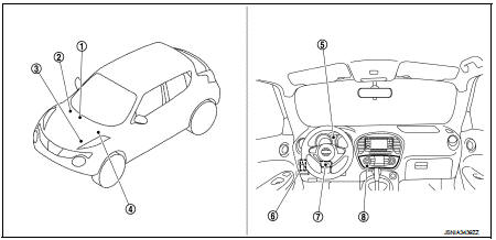
1. A/C auto amp.
Refer to HAC-12, "Component Parts Location".
2. ABS actuator and electric unit (control unit) Refer to BRC-9, "Component Parts Location" (without ESP) or BRC-97, "Component Parts Location" (with ESP).
3. ECM Refer to EC-25, "ENGINE CONTROL SYSTEM : Component Parts Location" (MR16DDT), EC-455, "ENGINE CONTROL SYSTEM : Component Parts Location" (HR16DE) or EC-813, "Component Parts Location" (K9K).
4. TCM Refer to TM-314, "CVT CONTROL SYSTEM : Component Parts Location" (CVT: RE0F11A) or TM-131, "CVT CONTROL SYSTEM : Component Parts Location" (CVT RE0F10A).
5. Combination meter
6. BCM
Refer to BCS-6, "BODY CONTROL
SYSTEM : Component Parts Location"
(with Intelligent Key system) or
BCS-96, "BODY CONTROL SYSTEM
: Component Parts Location"
(without Intelligent Key system).
7. EPS control unit Refer to STC-5, "Component Parts Location".
8. Multi display unit
Component Description


Multi Display Unit
• A multi display unit integrating a color display and an operation panel is adopted.
• It is connected to other units via CAN communication and performs the drive mode control, air conditioner control, display of various information, and various settings.
• The display can show the drive mode (NORMAL, SPORT, ECO), drive information (travel time, mileage, average vehicle speed), ECO information (fuel consumption history), setting screen as well as engine power, providing information on the vehicle status according to the driver's operation.
• For the operation switch section, newly developed unique switches are adopted, which respectively have 2 types of symbols and functions.

UNIQUE SWITCH
The switch integrates 2 types of LEDs*, filters that pass or absorb specified wavelengths (filter 1, filter 2), and filters adapted to both display colors (filter 3), enabling 2 different symbols to be displayed at a same position by LED changeover.
*: Abbreviation of light emitting diode. It is a semiconductor device that lights up when electric current is applied.
Operation description of unique switch
In drive mode
• LED1 lights up, the light from LED1 passes filter 1 and filter 3, and “ECO
INFO” is displayed.
In air conditioner mode
• LED2 lights up, the light from LED2 passes filter 2 and filter 3, and “
” is displayed.


 System
NISSAN dynamic control system
NISSAN DYNAMIC CONTROL SYSTEM : System Description
SYSTEM DIAGRAM
• *1: M/T models except for K9K engine models
• *2: CVT models
MULTI DISPLAY UNIT INPUT/OUTPUT SI ...
Other materials:
P0300, P0301, P0302, P0303, P0304 misfire
DTC Logic
DTC DETECTION LOGIC
When a misfire occurs, engine speed will fluctuate. If the engine speed
fluctuates enough to cause the crankshaft
position (CKP) sensor (POS) signal to vary, ECM can determine that a misfire is
occurring.
The misfire detection logic consists of the following t ...
The ambient temperature display is incorrect
Description
• The displayed ambient air temperature is higher than the actual
temperature.
• The displayed ambient air temperature is lower than the actual temperature.
Diagnosis Procedure
NOTE:
Check that the symptom is not applicable to the normal operating condition
before starting diagn ...
Roof side molding
Exploded View
1. Roof side molding
2. Roof side molding clip
3. Double-sided tape [t: 2.5 mm (0.098 in)]
4. Body side outer panel
5. Roof panel
: Vehicle front
: Do not reuse
Removal and Installation
REMOVAL
ROOF SIDE MODLDING
1. Disengage roof side molding rear side fixing clip, usi ...
