Nissan Juke Service and Repair Manual : Oil pan
Exploded View

1. Baffle plate
2. Gasket
3. Oil pan
4. O-ring
5. Drain plug
6. Oil level gauge guide
7. Transaxle
8. Crankshaft position sensor (POS)
 : N·m (kg-m, ft-lb)
 : N·m (kg-m, in-lb)
 : Always replace after every
disassembly.
Removal and Installation
REMOVAL
CAUTION:
Never drain engine oil when the engine is hot to avoid the danger of being
scalded.
1. Remove engine under cover.
2. Remove RH front wheel. Refer to WT-7, "Exploded View".
3. Remove fender protector RH. Refer to EXT-22, "Exploded View".
4. Remove engine mounting bracket. Refer to EM-326, "Exploded View".
5. Remove center bearing bracket as shown.

6. Remove A/C compressor bracket mounting bolt as shown.

7. Remove oil level gauge guide.
8. Drain engine oil. Refer to LU-34, "Draining".
CAUTION:
Perform when engine is cold.
9. Remove oil pan and transaxle joint bolts.
10. Support the engine bottom of the oil pan with a transmission jack etc.

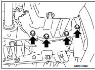
11. Remove oil pan bolt reverse order as shown.

• Insert seal cutter (special service tool) between upper oil pan and cylinder block. Slide tool by tapping on the side of the tool with a hammer.
CAUTION:
Exercise care not to damage mating surface.

12. Remove oil pan and baffle plate.
INSTALLATION
• Install in the reverse order of removal paying attention to the following.
1. Apply liquid gasket as shown.
• Use Genuine Liquid Gasket or equivalent.

2. Install baffle plate.
3. Install oil pan.
• Tighten the mounting bolts of oil pan on the clutch housing without locking.
• Tighten the bolts in the numerical order shown in the figure.
 : 14 N·m (1.4 kg-m, 10 ft-lb)

• Tighten the mounting bolts of oil pan on the clutch housing.
 : 44 N·m (4.5 kg-m, 10 ft-lb)
4. At least 30 minutes after oil pan is installed, pour engine oil.

Inspection
INSPECTION AFTER REMOVAL
Clean oil pump assembly if any object attached.
INSPECTION AFTER INSTALLATION
• Inspection the engine oil level. Refer to LU-33, "Inspection".
• Start the engine, and make sure there is no leak of engine oil. Refer to LU-33, "Inspection".
 Exhaust manifold
Exploded View
1. Exhaust gas temperature sensor 1
2. Gasket
3. Exhaust manifold
4. Exhaust gas pressure sensor 1
A. To cylinder head
: N·m (kg-m, ft-lb)
: Always replace after every
disas ...
 Glow plug
Exploded View
1. Glow plug
Engine front
: N·m (kg-m, ft-lb)
Removal and Installation
REMOVAL
CAUTION:
Remove glow plug only if necessary. If carbon adheres, it may be stuck and
broken.
1. ...
Other materials:
Intelligent Key
Replace the battery in the Intelligent Key as follows: 1. Remove the mechanical
key from the Intelligent Key.
2. Insert a small screwdriver into the slit of the corner and twist it to separate
the upper part from the lower part. Use a cloth to protect the casing.
3. Replace the battery with ...
Hood switch
Component Function Check
1.CHECK FUNCTION
1. Select “HOOD SW” in “Data Monitor” mode of “IPDM E/R” using CONSULT-III.
2. Check “HOOD SW” indication under the following condition.
Is the indication normal?
YES >> Hood switch is OK.
NO >> Go to SEC-155, "Diagnosis Procedure& ...
System (intelligent key system)
Intelligent key system : System Diagram
Intelligent key system : System Description
• The Intelligent Key system is a system that makes it possible to lock and
unlock the door locks (door lock/
unlock function) by carrying the Intelligent Key, which operates based on the
results of electron ...
