Nissan Juke Service and Repair Manual : Hood switch
Component Function Check
1.CHECK FUNCTION
1. Select “HOOD SW” in “Data Monitor” mode of “IPDM E/R” using CONSULT-III.
2. Check “HOOD SW” indication under the following condition.

Is the indication normal? YES >> Hood switch is OK.
NO >> Go to SEC-155, "Diagnosis Procedure".
Diagnosis Procedure
1.CHECK HOOD SWITCH SIGNAL CIRCUIT 1
1. Turn ignition switch OFF.
2. Disconnect hood switch connector.
3. Check voltage between hood switch harness connector and ground.

Is the inspection result normal? YES >> GO TO 3.
NO >> GO TO 2.
2.CHECK HOOD SWITCH SIGNAL CIRCUIT 2
1. Disconnect IPDM E/R connector.
2. Check continuity between IPDM E/R harness connector and hood switch harness connector

3. Check continuity between IPDM E/R harness connector and ground.
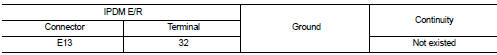
Is the inspection result normal? YES >> Replace IPDM E/R. Refer to PCS-34, "Removal and Installation".
NO >> Repair or replace harness.
3.CHECK HOOD SWITCH GROUND CIRCUIT
Check continuity between hood switch harness connector and ground.

Is the inspection result normal? YES >> GO TO 4.
NO >> Repair or replace harness.
4.CHECK HOOD SWITCH
Refer to SEC-156, "Component Inspection".
Is the inspection result normal? YES >> GO TO 5.
NO >> Replace hood switch.
5.CHECK INTERMITTENT INCIDENT
Refer to GI-42, "Intermittent Incident".
>> INSPECTION END
Component Inspection
1.CHECK HOOD SWITCH
1. Turn ignition switch OFF.
2. Disconnect hood switch connector.
3. Check continuity between hood switch terminals

Is the inspection result normal? YES >> INSPECTION END
NO >> Replace hood switch.
 B2110 shift position/clutch interlock switch
DTC Logic
DTC DETECTION LOGIC
NOTE:
If DTC B2110 is displayed with DTC U1000, first perform the trouble diagnosis
for DTC U1000. Refer to PCS-
30, "DTC Logic".
DTC CONFIRMATION PROC ...
 Horn function
Component Function Check
1.CHECK FUNCTION 1
1. Disconnect vehicle security horn relay.
2. Perform “VEHICLE SECURITY HORN” in “ACTIVE TEST” mode of “THEFT ALM” of “BCM”
using CONSULT-
III.
3. ...
Other materials:
Diagnosis system [ABS actuator and electric unit (control
unit)]
CONSULT-III Function
APPLICATION ITEMS
CONSULT-III can display each diagnostic item using the diagnostic test modes
as follows.
*1: The following diagnosis information is erased by erasing.
• DTC
• Freeze frame data (FFD)
*2: Although “Function Test” is selectable, do not use its.
ECU I ...
ECU diagnosis information
IPDM E/R
Reference Value
VALUES ON THE DIAGNOSIS TOOL
TERMINAL LAYOUT
PHYSICAL VALUES
*1: MR16DDT engine models
*2: Except MR16DDT engine models
*3: CVT models
*4: M/T models
*5: With daytime running light system
*6: Without daytime running light system
*7: K9K engine mo ...
Service data and specifications (SDS)
Wheel Bearing
Drive Shaft
2WD
*: For measuring position, refer to FAX-26, "WHEEL SIDE : Disassembly and
Assembly" (Wheel side), FAX-
29, "TRANSAXLE SIDE : Disassembly and Assembly" (Transaxle side).
4WD
*: For measuring position, refer to FAX-26, "WHEEL SIDE : ...
