Nissan Juke Service and Repair Manual : Ignition coil, spark plug and rocker cover
Exploded View

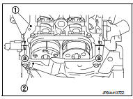
1. Ignition coil
2. Spark plug
3. Rocker cover
4. Hose cramp
5. PCV hose
6. PCV valve
7. O-ring
8. Gasket
9. Oil filler cap
10. O-ring
11. Camshaft position sensor (INT)
12. Camshaft position sensor (EXH)
13. Cramp
A. To intake manifold
 : Always replace after every
disassembly.
 : N·m (kg-m, in-lb)
 : N·m (kg-m, ft-lb)
 : Sealing point
 : Should be lubricated with oil.
Removal and Installation
REMOVAL
1. Remove intake manifold. Refer to EM-163, "Exploded View".
2. Remove ignition coil.
CAUTION:
• Never drop or shock ignition coil.
• Never disassemble ignition coil.
. Remove fuel tube protector. Refer to EM-173, "Exploded View".
4. Remove PCV hose from rocker cover.
5. Remove PCV valve, if necessary.
6. Remove rocker cover.
• Loosen bolts in reverse order as shown in the figure.
 : Engine front

7. Remove rocker cover gasket from rocker cover.
8. Use scraper to remove all traces of liquid gasket from cylinder head and front cover.
CAUTION:
Never scratch or damage the mating surface when cleaning off old liquid gasket.
INSTALLATION
1. Rocker cover with the following procedure: a. Press gasket onto the bosses for the rocker cover bolt holes as shown in the figure to prevent the rocker cover from dropping off.

b. Apply liquid gasket to the position as shown in the figure.
1 : Cylinder head
2 : Front cover
a : φ2.5 - 3.5 mm
Use Genuine Liquid Gasket or equivalent.
c. Install rocker cover to cylinder head.
CAUTION:
Check the gasket is not dropped.
• Tighten bolts in two steps separately in numerical order as shown in the figure.
: Engine front

2. Install PCV valve.
• Insert PCV valve until the flange of PCV valve contact the grommet absolutely.
3. Install in the reverse order of removal, for the rest of parts.
 Fuel injector and fuel tube
Exploded View
1. Stud bolt
2. O-ring (green)
3. Fuel injector (front)
4. Clip
5. Fuel injector (rear)
6. O-ring (black)
7. Fuel tube protector
8. Fuel tube
9. Fuel feed hose
10. Qui ...
 Timing chain
Exploded View
1. Timing chain slack guide
2. Timing chain tensioner
3. Camshaft sprocket (EXH)
4. Camshaft sprocket (INT)
5. Plug 6. Front oil seal
7. Crankshaft pulley
8. Crankshaft pull ...
Other materials:
P0846 transmission fluid pressure SEN/SW B
DTC Logic
DTC DETECTION LOGIC
DTC CONFIRMATION PROCEDURE
CAUTION:
Be careful of the driving speed.
1.PREPARATION BEFORE WORK
If another "DTC CONFIRMATION PROCEDURE" occurs just before, turn ignition
switch OFF and wait for at
least 10 seconds, then perform the next test.
&g ...
Push-button ignition switch position indicator
Description
Push-button ignition switch changes the power supply position.
BCM maintains the power supply position status.
BCM changes the power supply position with the operation of the push-button
ignition switch.
Component Function Check
1.CHECK FUNCTION
Check push-button ignition swi ...
Both side headlamps (HI) are not turned on
Description
Both side headlamps (HI) are not turned ON when setting to the lighting
switch HI or PASS.
Diagnosis Procedure
1.COMBINATION SWITCH INSPECTION
Check the combination switch. Refer to BCS-92, "Symptom Table".
Is the inspection result normal?
YES >> GO TO 2.
NO ...
