Nissan Juke Service and Repair Manual : Push-button ignition switch position indicator
Description
Push-button ignition switch changes the power supply position.
BCM maintains the power supply position status.
BCM changes the power supply position with the operation of the push-button ignition switch.
Component Function Check
1.CHECK FUNCTION
Check push-button ignition switch (“PUSH SWITCH INDICATOR”) in Active Test Mode with CONSULT-III.

Is the inspection result normal? YES >> INSPECTION END
NO >> Refer to PCS-111, "Diagnosis Procedure".
Diagnosis Procedure
1.CHECK PUSH-BUTTON IGNITION SWITCH INPUT SIGNAL
1. Turn ignition switch OFF.
2. Disconnect push-button ignition switch connector.
3. Check voltage between push-button ignition switch harness connector and ground.

Is the inspection normal? YES >> GO TO 2.
NO-1 >> Check 10 A fuse [No.13, located in fuse block (J/B)].
NO-2 >> Check harness for open or short between push-button ignition switch and fuse.
2.CHECK BCM INPUT
1. Connect push-button ignition switch connector.
2. Disconnect BCM connector.
3. Check voltage between BCM connector and ground.

Is the inspection normal? YES >> Replace BCM. Refer to BCS-93, "Removal and Installation".
NO >> GO TO 3.
3.CHECK PUSH-BUTTON IGNITION SWITCH CIRCUIT
1. Disconnect push-button ignition switch connector.
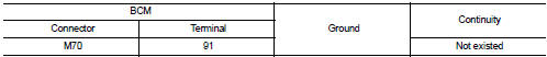
2. Check continuity between BCM harness connector and push-button ignition switch harness connector.

3. Check continuity between BCM harness connector and ground.
Is the inspection normal? YES >> Replace push-button ignition switch.
NO >> Repair or replace harness.
 Push-button ignition switch
Component Function Check
1.CHECK FUNCTION
1. Select “PUSH SW” in “Data Monitor” mode with CONSULT-III.
2. Check the push-button ignition switch signal under the following conditions.
Is the indi ...

Other materials:
B27B0 A/C auto AMP.
DTC Logic
DTC DETECTION LOGIC
NOTE:
• If DTC is displayed along with DTC U1000, first perform the trouble diagnosis
for DTC U1000. Refer to HAC-
141, "DTC Logic".
• If DTC is displayed along with DTC U1010, first perform the trouble diagnosis
for DTC U1010. HAC-142,
"DTC Log ...
Speed limiter main switch
Component Function Check
1.CHECK SPEED LIMITER MAIN SWITCH FUNCTION
1. Turn ignition switch ON.
2. Check the voltage between ECM harness connector terminals under the following
conditions
Is the inspection result normal?
YES >> INSPECTION END
NO >> Go to EC-1020, "Diagnosi ...
Symptom diagnosis
Squeak and rattle trouble diagnoses
Work Flow
CUSTOMER INTERVIEW
Interview the customer if possible, to determine the conditions that exist
when the noise occurs. Use the Diagnostic
Worksheet during the interview to document the facts and conditions when the
noise occurs and any of
the cu ...
