Nissan Juke Service and Repair Manual : Wiring diagram
4WD SYSTEM
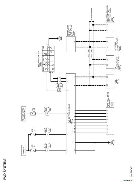
Wiring Diagram
For connector terminal arrangements, harness layouts, and alphabets in a
 (option abbreviation; if not
described in wiring diagram), refer to GI-12, "Connector Information/Explanation
of Option Abbreviation".
 ECU diagnosis information
4WD control module
Reference Value
VALUES ON THE DIAGNOSIS TOOL
TERMINAL LAYOUT
PHYSICAL VALUES
*: The values are changed by throttle opening and engine speed.
CAUTION:
When using ...
 Basic inspection
...
Other materials:
Rear seats
Folding
Before folding the rear seats:
Secure the seat belts on the seat belt hooks on the side wall. (See “Seat belt
hooks” .) To fold the seatback, pull the adjusting knob1 .
To return the seatback to the seating position, lift up each seatback and push
it to the upright position until it ...
P0201, P0202, P0203, P0204 fuel injector
DTC Logic
DTC DETECTION LOGIC
NOTE:
If DTC P0201, P0202, P0203 or P0204 is displayed with DTC P0263, P0266, P0269 or
P0272 first perform
trouble diagnosis for DTC P0263, P0266, P0269 or P0272. Refer to EC-931, "DTC
Logic".
Diagnosis Procedure
1.CHECK FUEL INJECTOR POWER SUPPLY ...
Precaution
Precaution for Supplemental Restraint System (SRS) "AIR BAG" and "SEAT
BELT
PRE-TENSIONER"
The Supplemental Restraint System such as “AIR BAG” and “SEAT BELT PRE-TENSIONER”,
used along
with a front seat belt, helps to reduce the risk or severity of injury to the
driver a ...