Nissan Juke Service and Repair Manual : System
Warning chime system
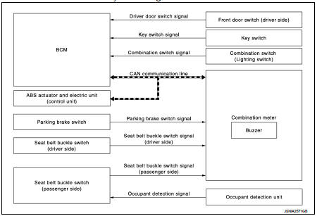
WARNING CHIME SYSTEM : System Diagram
WARNING CHIME SYSTEM : System Description
COMBINATION METER
The combination meter sounds the alarm buzzer installed in the combination meter when receiving the buzzer output signal transmitted from each unit.
BCM
BCM receives signals from various units and transmits a buzzer output signal to
the combination meter via
CAN communication if it judges that the warning buzzer should be activated.
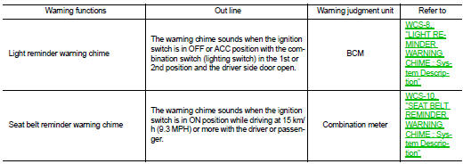
WARNING CHIME FUNCTION LIST

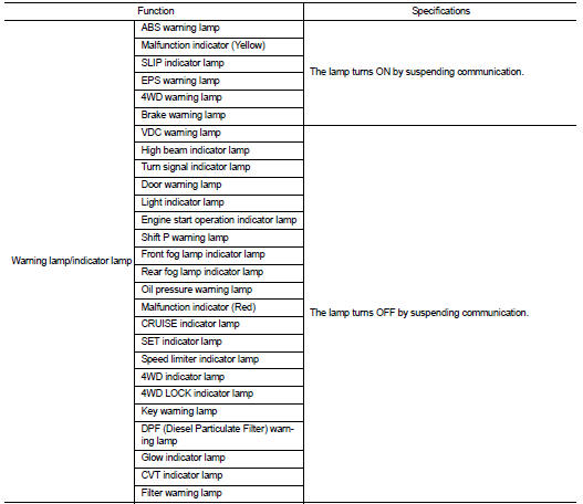
WARNING CHIME SYSTEM : Fail-Safe
FAIL-SAFE
The combination meter activates the fail-safe control if CAN communication with each unit is malfunctioning.

Light reminder warning chime
LIGHT REMINDER WARNING CHIME : System Dia

LIGHT REMINDER WARNING CHIME : System Description
WARNING CHIME OPERATION CONDITIONS
If all of the following conditions are fulfilled.

WARNING CHIME CANCEL CONDITIONS
Warning is canceled if any of the following conditions is fulfilled.

SIGNAL PATH
1. BCM requires warning chime output to combination meter when it judges light reminder warning chime is necessary from signals below.

2. Combination meter sounds integrated buzzer, following the warning chime output requirement (below signal) from BCM.

TIMING CHART

Seat belt reminder warning chime
SEAT BELT REMINDER WARNING CHIME : System Diagram

SEAT BELT REMINDER WARNING CHIME : System Description
WARNING OPERATION CONDITIONS
If all of the following conditions are fulfilled.

WARNING CANCEL CONDITIONS
Warning is canceled if any of the following conditions is fulfilled.

SIGNAL PATH
Combination meter sounds integrated buzzer when it judges that seat belt warning chime is necessary from signals below.

TIMING CHART

SOUND SPECIFICATION

Parking brake release warning chime
PARKING BRAKE RELEASE WARNING CHIME : System Diagram

PARKING BRAKE RELEASE WARNING CHIME : System Description
WARNING OPERATION CONDITIONS
If all of the following conditions are fulfilled.

WARNING CANCEL CONDITIONS
Warning is canceled if any of the following conditions are fulfilled.

SIGNAL PATH
Combination meter sounds integrated buzzer when it judges that parking brake release warning chime is necessary from signals below.

TIMING CHART

SOUND SPECIFICATION

Key warning chime
KEY WARNING CHIME : System Diagram

KEY WARNING CHIME : System Description
DESCRIPTION
The warning chime sounds when the ignition switch is in OFF or ACC position with the key inserted and the driver side door open.
WARNING OPERATION CONDITIONS
The BCM transmits the buzzer output signal to combination meter with CAN communication line when all of the following operation conditions are met. When combination meter receives buzzer output signal, it sounds the buzzer

WARNING CANCEL CONDITIONS
Warning is canceled if any of the following conditions is fulfilled.

SIGNAL PATH
1. BCM requires warning chime output to combination meter when it judges key warning chime is necessary from signals below.

2. Combination meter sounds integrated buzzer, following the warning chime output requirement (below signal) from BCM.

TIMING CHART

SOUND SPECIFICATION

 Component parts
Component Parts Location
1. Parking brake switch
2. Seat belt buckle switch (passenger
side)
3. Occupant detection unit
(Under the passenger seat cushion
pad)
4. ABS actuator and electric un ...
 Diagnosis system (combination meter)
Consult-III Function
CONSULT-III APPLICATION ITEMS
CONSULT-III can perform the following diagnosis modes via CAN communication
and the combination meter.
SELF DIAG RESULT
Refer to MWI-36, &quo ...
Other materials:
Parking lamp circuit
Without daytime running light system
WITHOUT DAYTIME RUNNING LIGHT SYSTEM : Component Function Check
1.CHECK PARKING LAMP OPERATION
CONSULT-III ACTIVE TEST
1. Select “EXTERNAL LAMPS” of IPDM E/R active test item.
2. With operating the test items, check that the parking lamp is turned ON.
TAIL ...
Sill cover
Exploded View
1. Screw grommet
2. Screw grommet
3. Sill cover
4. Wind defle
Removal and Installation
REMOVAL
1. Remove sill cover front end fixing screw (A).
2. Remove sill cover rear end fixing screw (A).
3. Remove sill cover lower side fixing screws.
4. Fully open front door and ...
System
POWER DISTRIBUTION SYSTEM
POWER DISTRIBUTION SYSTEM : System Description
SYSTEM DESCRIPTION
• PDS (POWER DISTRIBUTION SYSTEM) is the system that BCM controls with the
operation of the pushbutton
ignition switch and performs the power distribution to each power circuit. This
system is used in ...