Nissan Juke Service and Repair Manual : System
Starting system (with intelligent key) : System Diagram

*1: M/T models
*2: CVT models
Starting system (with intelligent key) : System Description
CVT MODELS
• When selector lever is P or N, power is supplied to starter relay and starter control relay by transmission range switch. And BCM and IPDM E/R (CPU) detect selector lever P/N condition by the inputted signal.
• When starter operating condition is satisfied, IPDM E/R turns starter control relay ON by starter control relay control signal.
• When engine cranking condition is satisfied, BCM turns starter relay ON by starter control relay control signal.
• Then battery power is supplied to starter motor (“S” terminal) through starter control relay and starter relay.
M/T MODELS
• When the ignition switch is turned ON or START position power is supplied to starter relay and starter control relay. And BCM and IPDM E/R (CPU) detect ignition switch position by the inputted signal.
• When starter operating condition is satisfied, IPDM E/R turns starter control relay ON by starter control relay control signal.
• When engine cranking condition is satisfied, BCM turns starter relay ON by starter control relay control signal.
• Then battery power is supplied to starter motor (“S” terminal) through starter control relay and starter relay.
Starting system (without intelligent key) : System Diagram
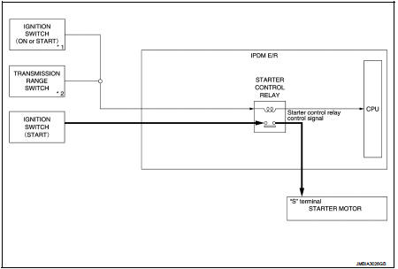
*1: M/T models
*2: CVT model
Starting system (without intelligent key) : System Description
CVT MODELS
• When selector lever is P or N, power is supplied to starter control relay by transmission range switch. And IPDM E/R (CPU) detect selector lever P/N condition by the inputted signal.
• When engine cranking condition is satisfied, then battery power is supplied to starter motor (“S” terminal) through starter control relay.
M/T MODELS
When ignition switch is START position, battery power is supplied to starter motor (“S” terminal).
 Component parts
Starting system (with intelligent key) : Component Parts Location
1. IPDM E/R
Refer to PCS-5, "Component Parts
Location".
2. Transmission range switch (CVT
models)
Refer to TM-131, & ...
 Wiring diagram
...
Other materials:
Air cleaner and air duct
Exploded View
1. Mass air flow sensor
2. Gasket
3. Clamp
4. Air duct (suction side)
5. Clamp
6. Air cleaner cover assembly
7. Mounting rubber
8. Air cleaner filter
9. Air cleaner body assembly
10. Air duct with resonator
11. Grommet
12. Air duct (duct side)
13. Grommet
14. B ...
Rear seats
Folding
Before folding the rear seats:
Secure the seat belts on the seat belt hooks on the side wall. (See “Seat belt
hooks” .) To fold the seatback, pull the adjusting knob1 .
To return the seatback to the seating position, lift up each seatback and push
it to the upright position until it ...
Back door does not opened
Diagnosis Procedure
1.CHECK BACK DOOR OPENER SWITCH
Check back door opener switch.
Refer to DLK-513, "Component Function Check".
Is the inspection result normal?
YES >> GO TO 2.
NO >> Repair or replace the malfunctioning parts.
2.CHECK BACK DOOR OPENER ACTUATOR
...