Nissan Juke Service and Repair Manual : Super lock actuator
Driver side : Component Function Check
1.CHECK FUNCTION
1. Select “DOOR LOCK” of “BCM” using CONSULT-III.
2. Select “SUPER LOCK” in “ACTIVE TEST” mode.
3. Check that the function operates normally according to the following conditions.

Is the inspection result normal? YES >> Super lock actuator is OK.
NO >> Refer to DLK-99, "DRIVER SIDE : Diagnosis Procedure".
Driver side : Diagnosis Procedure
1.CHECK SUPER LOCK ACTUATOR INPUT SIGNAL
1. Turn ignition switch OFF.
2. Disconnect front door lock assembly (driver side) connector.
3. Check voltage between front door lock assembly (driver side) harness connector and ground.

Is the inspection result normal? YES >> Replace front door lock assembly (driver side).
NO >> GO TO 2.
2.CHECK SUPER LOCK ACTUATOR CIRCUIT
1. Disconnect BCM connector and all door lock assembly connector.
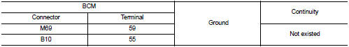
2. Check continuity between BCM harness connector and front door lock assembly (driver side) harness connector.

3. Check continuity between BCM harness connector and ground

Is the inspection result normal? YES >> GO TO 3.
NO >> Repair or replace harness.
3.CHECK BCM OUTPUT SIGNAL
1. Connect BCM connector.
2. Check voltage between BCM harness connector and ground.

Is the inspection result normal? YES >> Check for internal short of each super lock actuator.
NO >> Replace BCM. Refer to BCS-93, "Removal and Installation".
Passenger side : Component Function Check
1.CHECK FUNCTION
1. Select “DOOR LOCK” of “BCM” using CONSULT-III.
2. Select “SUPER LOCK” in “ACTIVE TEST” mode.
3. Check that the function operates normally according to the following conditions.

Is the inspection result normal? YES >> Super lock actuator is OK.
NO >> Refer to DLK-100, "PASSENGER SIDE : Diagnosis Procedure".
Passenger side : Diagnosis Procedure
1.CHECK SUPER LOCK ACTUATOR INPUT SIGNAL
1. Turn ignition switch OFF.
2. Disconnect front door lock assembly (passenger side) connector.
3. Check voltage between front door lock assembly (passenger side) harness connector and ground.

Is the inspection result normal? YES >> Replace front door lock assembly (passenger side).
NO >> GO TO 2.
2.CHECK SUPER LOCK ACTUATOR CIRCUIT
1. Disconnect BCM connector and all door lock assembly connector.
2. Check continuity between BCM harness connector and front door lock assembly (passenger side) harness connector

3. Check continuity between BCM harness connector and ground.
Is the inspection result normal? YES >> GO TO 3.
NO >> Repair or replace harness.
3.CHECK BCM OUTPUT SIGNAL
1. Connect BCM connector.
2. Check voltage between BCM harness connector and ground.

Is the inspection result normal? YES >> Check for internal short of each super lock actuator.
NO >> Replace BCM. Refer to BCS-93, "Removal and Installation".
Rear LH : Component Function Check
1.CHECK FUNCTION
1. Select “DOOR LOCK” of “BCM” using CONSULT-III.
2. Select “SUPER LOCK” in “ACTIVE TEST” mode.
3. Check that the function operates normally according to the following conditions.

Is the inspection result normal? YES >> Super lock actuator is OK.
NO >> Refer to DLK-101, "REAR LH : Diagnosis Procedure".
Rear LH : Diagnosis Procedure
1.CHECK SUPER LOCK ACTUATOR INPUT SIGNAL
1. Turn ignition switch OFF.
2. Disconnect rear door lock assembly LH connector.
3. Check voltage between rear door lock assembly LH harness connector and ground.

Is the inspection result normal? YES >> Replace rear door lock assembly LH.
NO >> GO TO 2.
2.CHECK SUPER LOCK ACTUATOR CIRCUIT
1. Disconnect BCM connector and all door lock assembly connector.
2. Check continuity between BCM harness connector and rear door lock assembly LH harness connector.

3. Check continuity between BCM harness connector and ground

Is the inspection result normal? YES >> GO TO 3.
NO >> Repair or replace harness.
3.CHECK BCM OUTPUT SIGNAL
1. Connect BCM connector.
2. Check voltage between BCM harness connector and ground.

Is the inspection result normal? YES >> Check for internal short of each super lock actuator.
NO >> Replace BCM. Refer to BCS-93, "Removal and Installation".
Rear RH : Component Function Check
1.CHECK FUNCTION
1. Select “DOOR LOCK” of “BCM” using CONSULT-III.
2. Select “SUPER LOCK” in “ACTIVE TEST” mode.
3. Check that the function operates normally according to the following conditions.

Is the inspection result normal? YES >> Back door lock actuator is OK.
NO >> Refer to DLK-103, "REAR RH : Diagnosis Procedure".
Rear RH : Diagnosis Procedure
1.CHECK SUPER LOCK ACTUATOR INPUT SIGNAL
1. Turn ignition switch OFF.
2. Disconnect rear door lock assembly RH connector.
3. Check voltage between rear door lock assembly RH harness connector and ground.

Is the inspection result normal? YES >> Replace rear door lock assembly RH.
NO >> GO TO 2.
2.CHECK SUPER LOCK ACTUATOR CIRCUIT
1. Disconnect BCM connector and all door lock assembly connector.
2. Check continuity between BCM harness connector and rear door lock assembly RH harness connector.

3. Check continuity between BCM harness connector and ground.

Is the inspection result normal? YES >> GO TO 3.
NO >> Repair or replace harness.
3.CHECK BCM OUTPUT SIGNAL
1. Connect BCM connector.
2. Check voltage between BCM harness connector and ground.

Is the inspection result normal? YES >> Check for internal short of each super lock actuator.
NO >> Replace BCM. Refer to BCS-93, "Removal and Installation".
 Shift P warning lamp
Component Function Check
1.CHECK FUNCTION
1. Select “INTELLIGENT KEY” of “BCM” using CONSULT-III.
2. Select “LCD” in “ACTIVE TEST” mode.
3. Check that the function operates normally according to t ...
 Unlock sensor
Component Function Check
1.CHECK FUNCTION
1. Select “INTELLIGENT KEY” of “BCM” using CONSULT-III.
2. Select “UNLK SEN -DR” in “DATA MONITOR” mode.
3. Check that the function operates normally acco ...
Other materials:
Hazard switch
Component Function Check
1.CHECK HAZARD SWITCH SIGNAL BY CONSULT-III
CONSULT-III DATA MONITOR
1. Turn the ignition switch ON.
2. Select “HAZARD SW” of BCM (FLASHER) data monitor item.
3. With operating the hazard switch, check the monitor status.
Is the inspection result normal?
YES >> ...
B210E starter relay
DTC Logic
DTC DETECTION LOGIC
NOTE:
• If DTC B210E is displayed with DTC U1000, first perform the trouble diagnosis
for DTC U1000. Refer to
PCS-30, "DTC Logic".
• If DTC B210E is displayed with DTC B2605, first perform the trouble diagnosis
for DTC B2605. Refer to
SEC-90, "D ...
Front power window switch (passenger side)
Component Function Check
1. CHECK FRONT POWER WINDOW SWITCH (PASSENGER SIDE) FUNCTION
Check front power window motor (passenger side) operation with front power
window switch (passenger side).
Is the inspection result normal?
YES >> INSPECTION END
NO >> Refer to PWC-22, "Di ...