Nissan Juke Service and Repair Manual : Steering column
Exploded View

1. Cover
2. Sub-harness
3. Band
4. Steering column assembly
5. Slide plate (inner)
6. Slide plate (outer)
7. Bracket
 Always replace after every
disassembly.
 : N·m (kg-m, ft-lb)
 : N·m (kg-m, in-lb)
Removal and Installation
REMOVAL
CAUTION:
• While removing the steering column assembly, never unlock the tilt lever.
• Never impact on the axis when removing steering column assembly.
• Be careful when removing steering column assembly from the vehicle because it is heavy.
• Keep steering column assembly away from magnetic sources.
• Never disassemble steering column assembly. It is not separable.
• While removing the steering column assembly, never move the steering gear.
• When removing the steering column assembly, be careful not to allow the intermediate shaft to turn
.
1. Set vehicle to the straight-ahead position.
2. Place the tilt to the lowest level.
3. Remove instrument lower panel. Refer to IP-13, "Removal and Installation".
4. Remove driver air bag module. Refer to SR-13, "Removal and Installation".
5. Remove steering wheel. Refer to ST-9, "Removal and Installation".
6. Remove steering column cover. Refer to IP-13, "Removal and Installation".
7. Remove spiral cable. Refer to SR-16, "Removal and Installation".
8. Remove combination switch. Refer to BCS-162, "Removal and Installation". (without intelligent key system) or BCS-94, "Removal and Installation" (with intelligent key system).
9. Disconnect each switch harness connectors installed to steering column assembly.
10. Remove intermediate shaft mounting bolt (steering column side), and separate intermediate shaft from steering column assembly. Refer to ST-14, "Removal and Installation".
CAUTION
:
• Place a matching mark on both intermediate shaft and steering column assembly
before removing
intermediate shaft.
• When removing intermediate shaft, never insert a tool, such as a screwdriver, into the yoke groove to pull out the intermediate shaft. In case of the violation of the above, replace intermediate shaft with a new one.
11. Disconnect EPS control unit connectors.
12. Remove steering column assembly.
CAUTION:
When removing the mounting, be careful not to drop the steering column assembly.
13. Remove slide plate (outer and inner) from steering column assembly.
14. Remove cover, sub-harness, band, and bracket from steering column assembly.
CAUTION:
Remove cover, sub-harness, band, and bracket only when necessary.
15. Perform inspection after removal. Refer to ST-11, "Inspection".
INSTALLATION
CAUTION:
• Never impact on the axis when removing steering column assembly.
• When installing the steering column cover, check that the vehicle harness is not stuck in the cover.
Note the following, and install in the reverse order of removal.
• After tightening mounting nut (A) of the steering column assembly, press in slide plate (outer and inner) (1) to tighten mounting nut (B).
CAUTION:
The slide plate must be securely pressed in before tightening
the nut of slide plate (outer and inner).
• For intermediate shaft mounting bolt direction, refer to ST-13, "Exploded View". (Do not insert it from the other side.)

• When connecting intermediate shaft upper side (1) and column shaft, make sure the bolt is securely seated in groove (A) of column shaft (A) before final tightening.
• After installing steering column assembly, perform self-diagnosis with CONSULT-III to ensure correct operation. Refer to STC-10, "CONSULT-III Function".
• Never reuse band.
• Perform inspection after installation. Refer to ST-11, "Inspection".

Inspection
INSPECTION AFTER REMOVAL
• Check each part of steering column assembly for damage or other malfunctions. Replace if there are any abnormal conditions.
• Measure steering column assembly rotating torque using a preload gauge (A) (SST: ST3127S000). Replace steering column assembly if the rotating torque is outside the standard.
Rotating torque : Refer to ST-23, "Steering Column Operating Range".

• Measure the length “L” shown in the figure, if vehicle has been involved in a minor collision. Replace steering column assembly (with motor, reduction gear, sensor) if “L” is outside the standard.
L : Refer to ST-23, "Steering Column Operating Range".

INSPECTION AFTER INSTALLATION
• Check each part of steering column assembly for damage or other malfunctions. Replace if there are any abnormal conditions.
• Check the steering wheel play, neutral position steering wheel, steering wheel turning force, and front wheel turning angle. Refer to ST-8, "Inspection".
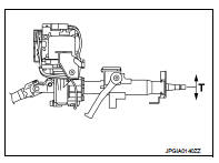
• Check tilt mechanism operating range “T” shown in the figure.
T : Refer to ST-23, "Steering Column Operating Range".
 Steering wheel
Exploded View
1. Steering wheel
: Always replace after every
disassembly.
: N·m (kg-m, ft-lb)
Removal and Installation
REMOVAL
NOTE:
When reconnecting spiral cable, fix cable with a tape so ...
 Steering shaft
Exploded View
LHD models
1. Dash seal
2. Guide*
3. Intermediate shaft
: Vehicle front
: N·m (kg-m, ft-lb)
*: If reinstalling, this part is not required.
RHD models
1. Dash seal
2. Gui ...
Other materials:
Shift P warning lamp
Component Function Check
1.CHECK FUNCTION
1. Select “INTELLIGENT KEY” of “BCM” using CONSULT-III.
2. Select “LCD” in “ACTIVE TEST” mode.
3. Check that the function operates normally according to the following
conditions.
Is the inspection result normal?
YES >> Shift P warning lamp is ...
U1000 can comm
Description
CAN (Controller Area Network) is a serial communication line for real time
applications. It is an on-vehicle multiplex
communication line with high data communication speed and excellent error
detection ability. Modern
vehicle is equipped with many electronic control unit, and eac ...
Engine control system
Symptom Table
SYSTEM — BASIC ENGINE CONTROL SYSTEM
1 - 6: The numbers refer to the order of inspection.
(continued on next page)
SYSTEM — ENGINE MECHANICAL & OTHER
1 - 6: The numbers refer to the order of inspection. ...